Chapter 20: Improvements in Equipment
As in other aspects of the Engineer effort to ready troops for war, the attack on Pearl Harbor brought about no sudden break or shift in the program for developing equipment. Pearl Harbor found the Engineers in the midst of a number of studies that needed to be brought to a successful conclusion. On top of these came new assignments as a result of new Engineer missions. Although commitment of American troops overseas affected the program to some extent from the beginning, it was not until mid-1943 that battle lessons became the dominant influence.
The Over-all Program
During the war years the Engineer Board had a great deal more money to spend on the development of equipment than had been available previously. In the fiscal year 1943 the board expended over six million dollars—almost three times as much as it had been allotted in the eighteen months before Pearl Harbor. More employees could be hired. As of 30 June 1941 there were 38 officers and 453 civilians on duty; a year later the number of officers and enlisted men had increased to 124 and the number of civilians to 821. Facilities, too, were at last adequate. By July 1942, eighteen of twenty-four new buildings had been completed.
Some assignments of a specialized nature could be handled more expeditiously at locations other than Belvoir. By the summer of 1943 the Engineer Board had established field offices at the following locations: Desert Warfare Training Center, Camp Young, California (desert roads); Mountain Training Center, Camp Hale, Colorado (mountain warfare equipment); U.S. Naval Amphibious Training Base, Fort Pierce, Florida (beach and underwater obstacles); Martha’s Vineyard, Massachusetts (amphibious equipment); Barrage Balloon Training Center, Memphis and Camp Tyson, Tennessee; Imperial Dam, Yuma, Arizona (bridge tests); and Seattle, Washington (camouflage studies).
Within this framework of more funds, facilities, and personnel, the Engineer Board looked forward to an expanding and urgent program. The number of development projects had increased slightly by June 1942 from the 99 remaining open at the end of the previous year to 117. This count was shortly thereafter artificially raised by a revision in the system of numbering. The new numbering system broke down the 117 projects into their components. Thus, what had been one project under MP 235, Organization and Equipment of Topographic Battalions, now became six, with project MP 235 A, Table of Organization and Table of Basic Allowances, project MP 235 B, Military Level, and so on. According to the new method of counting, the Engineer
Board had 600 active projects in the summer of 1942.1
About this time, various higher echelons of command began to challenge the desirability of an expanding development program and attempted to siphon off some of the energies being expended on it into the production of equipment already selected. In June 1942, the Army and Navy Munitions Board notified the Corps of Engineers that procurement of pilot models would be granted only AA-3 priority, the higher ratings to “be reserved for the production of end munitions items now urgently needed for the current conduct of the war.” The ANMB turned a deaf ear to the Engineers’ objection that this order would slow down their attempts to carry out the many assignments recently received. The outbreak of war made the search for new and better equipment a less important task than getting previously selected items into the hands of the troops.2 Sounding a similar note a few months later, Fowler cautioned the Engineer Board against losing sight of the end-all of the development program—“the issuing of suitable equipment in quantity to the troops in the field. ... Efforts should be directed not toward obtaining the best item in the world,” he admonished, “but toward obtaining in quantity a suitable article. ... Personnel working on development should continually ask themselves, ‘Is this article good enough to be put in quantity production without further refinement?’”3
If the assignment of lower priorities and Fowler’s restatement of principles served as a general indicator of the way the wind was blowing, the conclusions of a group of officers appointed to study the board’s program in July 1942 definitely established the new trend—the contraction of the development program as a whole with an eye to the speedy completion of essential work. After reviewing all currently active projects these officers recommended the immediate closing of 208 out of 613. Although their recommendation was carried out and although the Engineer Board and OCE officials attempted to screen projects carefully, more officers continued to be assigned to the board and more civilians to be hired. By February 1943, with total active projects at 448, the number of civilian employees stood at 1,342, a 64 percent increase during the previous eighteen months. At this point SOS stepped in, demanding a cut not only in projects but in staff.4
In March 1943, representatives of OCE and the Engineer Board sat down with the chief of ASF’s Development Branch to decide which projects could be dropped. The Engineers emerged from this conference having agreed to eliminate 183. By the end of May the board was carrying only 218 projects. Still ASF was not satisfied. On 31 July, Somervell called for further scrutiny:
Prior to and during the early stages of the present war the matter of research and development was of the greatest importance because of the dearth of modern munitions. Because of the great progress that has been made in this field and the substantial production now being realized in up-to-date weapons
and equipment, a review of the situation is indicated.
Although it is not desired to take any action which will curtail the development of those important items of munitions which give promise of substantially assisting in the war effort, it is considered imperative to restrict all future development to items of this category.5
In reply, Reybold insisted that all possible precautions were being taken to insure the attainment of ASF’s objective. Before a project was assigned, the Troops Division first determined whether the proposed development was essential to the prosecution of the war. Clearance by the Technical Committee and authorization by ASF followed, and finally the Engineering Division reviewed the plan of development as proposed by the Engineer Board. In conclusion Reybold reviewed the substantial reduction that had taken place since the first of January. The Engineer Board was now carrying less than a third of its former work load. From 391 projects at the beginning of the year it had dropped to 123 as of the end of August. To be sure, reductions in staff had not kept pace with reductions in projects, but with a total of 966, the number of military and civilian employees was about the same as in June 1942. This, argued Reybold, was “an absolute minimum working strength” because the board’s work encompassed more than development of new equipment. Its personnel conducted engineering studies, prepared plans and specifications, analyzed criticisms of equipment received from the field, and supervised service tests. Engineer participation in the drive to find substitutes for materials in short supply was centered at the board. About 25 percent of the board’s work was on so-called service projects. Some of this work, the procurement of pilot models, for example, could be farmed out to field offices. Experiments toward this end had, in fact, begun. But Reybold pointed out the limitations of decentralization: a central authority had to coordinate and standardize the work done in the field and this authority was the Engineer Board.6
Although thus defending the operations of the board, the Engineers changed its topside administrative staff. Heretofore, the president of the Engineer Board had occupied another position of importance at Belvoir. Brig. Gen. Edwin H. Marks, who had been appointed president on 1 July 1942, was at the same time Commanding General, Fort Belvoir. In October 1943, General Schulz was transferred from command of the EUTC at Claiborne to the presidency of the Engineer Board. He had no other duties. The following month a new executive officer, Col. William J. Matteson, replaced Col. Peter P. Goerz, who had served in that capacity for about a year. Schulz and Matteson remained with the board until the end of the war.
The fact that the Engineers found it possible to cut back their program for the development of new equipment was a tribute to the work that had been accomplished during the years preceding the Japanese attack. Those years witnessed the revolution in equipment. The developments that took place during the war years were on the whole less basic in nature. Much time and effort on the part of the board, of OCE, and of manufacturing concerns was expended in designing acetylene, nitrogen, and oxygen generators after the Corps of Engineers was asked to form gas generating
detachments in the spring of 1942. Similar efforts went into the perfection of water supply equipment, the Engineer Board working closely with industry in the development of purification units, distillation units, storage tanks and trucks, pumps, and well drilling rigs.7 Tests of landing mats continued, with particular emphasis upon the behavior of these mats under varying conditions of soil and weather. A group of experts from the Engineering Division, OCE, and from the Waterways Experiment Station at Vicksburg, Mississippi, lent much valuable assistance in the conduct of these tests. This group had investigated the subject of soil bearing capacity in an effort to provide permanent runways that would support the increasingly heavy bombers. Although mainly applicable to the construction undertaken by the Corps of Engineers for the AAF in the United States, the design criteria developed were also made available to theater Engineers.8
By spring 1943 the board’s earlier decision to concentrate on developing one allpurpose mat had been vindicated. Theater commanders reported that all airfields had to support heavy as well as light planes. The Engineer Board continued to point out the deficiencies of the pierced plank mat. Precious steel was wasted in its fabrication. In wet weather, mud and water seeped onto its surface causing it to become dangerously slippery. The pierced plank mat had a tendency to bend and to curl at the edges after a relatively short period of use by heavy bombers. By March 1943 the board had become convinced that these deficiencies outweighed the fact that the pierced plank mat could be produced in greater quantity than any other type and took up less cargo space. Production of pierced plank mat should be reduced. Additional requirements were to be satisfied by the heavy bar and rod mat. This type took up a large amount of shipping space and had been known to break when subjected to unusual strain, but it possessed a higher strength-weight ratio, was easier to lay and to camouflage, and was more skid-resistant than the pierced plank mat.9 Despite the board’s recommendation the pierced plank mat continued to be the type requested by theater commanders. It was the type they knew most about, deficiencies and all. Even while listing its imperfections and calling for improvements after the war was over, the Engineers admitted that the pierced plank mat “turned in a creditable performance through-out the world.”10 In seeking to improve what theater commanders had found to be generally satisfactory, the Engineer Board indulged the naturally perfectionist, but time-consuming and expensive, attitude of the research agency, which ASF and OCE were attempting to curb. By and
large, however, the board’s work during the war years arose directly out of needs resulting from the character of operations overseas.
Among the predictions which the Engineers had made as to the tactical nature of mobile warfare none turned out more nearly true than the ones on employment of obstacles to impede the advance. Months before American troops were committed to combat, the Army knew what to expect. From the Russian front and from the British in North Africa the evidence piled up: land mines were being used extensively and effectively by armies in retreat. American experience in North Africa offered further unhappy confirmation. Rommel had strewn large numbers of antitank and antipersonnel mines which enabled him to keep ahead of his pursuers for a long time. In Italy the enemy, grown more desperate, resorted to all the delaying tactics that terrain and available resources permitted. There, as Eisenhower described it in his memoirs, the German, in yielding “even a foot of ground ... made certain that every culvert and bridge on the miserable roads was blown out; every shelf road cut into the steep mountainsides was likewise destroyed.”11 In the Pacific theater nature itself had provided so many obstacles that the Japanese were saved the trouble of creating a large number of artificial ones, but by exploiting to the utmost what was ready-made, they were able to maintain a formidable resistance to the American advance.
Clearance of Land Mines and Other Obstacles
The Corps of Engineers pursued several lines of investigation in an effort to provide means of clearing a passage through land mines, barbed wire, and similar defenses which the enemy prepared and which he normally covered by artillery or infantry fire. The problem in dealing with land mines was not, of course, simply one of clearance. Since land mines were usually buried, a large part of the work of clearing them was discovering their exact location. Development of a portable mine detector—SCR 625—had been all but completed before Pearl Harbor and procurement of the first 1,000 units began early in 1942. Time was to show that SCR 625, while basically a good instrument, could not always be relied upon even to perform tasks for which it was specifically designed. But in the early months of 1942 techniques for detecting mines were far ahead of techniques for clearing mine fields and other obstacles under hostile fire.12
The greatest progress in clearance techniques had been in the area of explosives. Late in 1941, learning that the TVA wished to destroy several bridges and other structures, the Corps of Engineers sought and received permission to carry out this work. A company of engineers under the command of Lt. Alfred G. Hoel, Jr., who was to become the Engineer Board’s principal demolitions expert, spent a month in the Tennessee Valley trying out and keeping a detailed record of the types, amounts, methods of placement, and relative effectiveness of various explosives. Bangalore torpedoes seemed the best of the lot.
The bangalore torpedo, invented by a British Army officer in Bangalore, India, before World War I, was a metal tube which could be made up in various sizes and filled in the field with various combinations of
explosives. After the test in the Tennessee Valley, the Engineer Board’s Demolition and Obstacle Branch worked closely with the Ensign-Bickford Company, the Niles Steel Products Division of Republic Steel Corporation, the American Can Company, the Atlas Powder Company, and DuPont in an effort to determine the ideal size and content of explosive. By the spring of 1942 this cooperation had resulted in a prefabricated bangalore torpedo five feet long and two inches in diameter, containing about 8½ pounds of ammonium nitrate, and fitted with a copper well for the reception of a blasting cap or other detonating device. In addition to spurring the effort to improve the design of the bangalore torpedo, Hoel’s work in the Tennessee Valley contributed much useful information about the proper use of blasting caps, the hooking of circuits, and safety precautions.
Interest next shifted to Aberdeen Proving Ground, Maryland, where Ordnance and Engineers cooperated in erecting an antitank obstacle course. The Engineer Board’s report of the tests at Aberdeen contained detailed instructions for demolishing as well as for constructing log blocks, tetrahedrons, hedgehogs, and steel sheet and timber piling.
More dramatic in background and more productive of new methods of demolitions was a highly secret project to parachute a force into Norway and destroy its power plants. The personal interest of Roosevelt and Churchill and their assistants, Harry L. Hopkins and Mountbatten, caused an extraordinary amount of activity in the late spring and summer of 1942. Before the Norway enterprise was canceled several new explosives had been discovered, methods of packaging explosives vastly improved, and a well-nigh foolproof delay detonator developed.13
While these general investigations were under way, the Engineer Board directed attention to the more specific problem of clearance of mine fields. At this time troops were being taught to loosen mines with a probe and either to remove them one by one by hand or explode them one by one with TNT, a slow and dangerous method. What was desired was a means of removing a number of mines at once without exposing troops either to the mines themselves or to the enemy’s covering fire. A beginning in this direction was reported on 4 March 1942 by Maj. William F. Powers, chief of the Demolition and Obstacle Branch. Following a British lead, Powers proposed to join together a number of bangalore torpedoes to be pushed onto the mine field from a covered position, then detonated.14
Adoption of a special vehicle, or a special attachment for a standard vehicle, equipped either to excavate or explode mines remained a possibility in the spring of 1942. But the Engineers, while eagerly examining many proposals along this line, had found nothing worth investigating seriously. The Corps of Engineers shared this responsibility with the Ordnance Department, Ordnance being generally in charge of the
development of mechanical, and the Engineers, explosive, means for clearing mine fields. Ordnance had made little progress either. Models of two mechanical mine exploder devices had been produced, but neither was acceptable.
A year later, the Army was only slightly better off. Tests of the bangalore torpedo had, to be sure, confirmed the British report of its effectiveness against the type of German mines so far encountered, but it proved incapable of clearing a sufficiently wide gap when employed against the more blast-resistant mines already adopted by the American Army. Because the Germans might put a highly blast-resistant mine into the field also, the Engineer Board began, in January 1943, to experiment with a Canadian mine clearing device called a snake. The snake packed more explosive into its three-inch pipe than had the series of bangalores and since it was designed to be pushed forward by a tank, provided greater protection against defensive small arms fire. In addition to procuring a facsimile of the Canadian snake, the Engineer Board called upon several manufacturers to suggest ways to improve it. The Armco International Corporation devised a specially shaped snake made of longitudinally corrugated sheets into which cartridges of explosive were to be packed and bolted in the field. The Armco snake outperformed the Canadian prototype in firing the German mines, but also lacked effectiveness against American mines.
Even with this defect, the snake was the best device offered in July 1943 when representatives of NDRC, Ordnance, and Engineers sat down to review the status of their work. The best that could be said for the various appendages developed by the Ordnance Department for tanks—disk rollers, drums, drag weights, and a flail device modeled on the British scorpion—was that some showed promise.15
The possibility of excavating instead of exploding mines had also been tried out. In January 1942, 1st Lt. George M. Hays of the Coast Artillery School had suggested mounting a bulldozer blade on a tank. The advantages were significant—rapid operation by a small crew with gun protection. Maj. Karl F. Eklund, who supervised the Mechanical Equipment Section at the Engineer Board, believed the tank dozer would be a long time in the making, if, indeed, it could be developed at all. He had been following the attempts of the Desert Warfare Center to mount V-shaped blades on tanks for road construction work and had noted that all their experiments had resulted in failure. The fundamental idea had so much merit, however, that he and others at the board recommended that it be attacked from another angle as well. The British, whose bulldozer operators had had to work under fire, had already embarked upon a program to armor tractors. Accordingly the board requested authorization to develop armored tractors at the same time it was collaborating with Ordnance on the development of the tank dozer. SOS did not assent. Steel plate was so scarce in the summer of 1942 as to make it improbable that any could be diverted for this purpose, Clay observed in
refusing to approve the project, but work on the tank dozer should continue.16
Working first with the producers of tractor blades—LeTourneau and LaPlante-Choate—Eklund and the board’s project engineer, William J. Murwin, next enlisted the aid of the Ordnance Department in mounting various blades on tanks. By the spring of 1943 the cooperation of industry and of the two services had resulted in two models, one produced by LaPlante-Choate and the other by LeTourneau. Both of these excavators were V-blades with teeth, and thus operated more like a plow than a bulldozer. Despite much improvement in operation over the V-blades tested at the Desert Warfare Center, these tank dozers appeared scarcely more promising than the snake, the scorpion, or any of the other mine field clearing devices still under consideration. Yet the fact had been established that the medium tank could handle the dead load of a dozer blade and that its traction enabled it to knock over substantial barriers.17
The importance of an armored bulldozer was highlighted almost as soon as its capabilities were discovered, when, during the summer of 1943, reports like the following one from New Georgia began to come in:
... the blazing of Jeep trails was of prime importance. Construction of these trails through the jungle allowed food, ammunition, and supplies to be carried up to the most advanced Infantry lines.
A platoon of combat Engineers was assigned to each Infantry Combat team, for this purpose. ... Due to the type of fighting in this area, the “front-lines” at times were everywhere, and at times the dozer operated in front of the Infantry lines. It soon became a special target for Jap snipers and Jap machine gunners, who waited for its appearance in ambush, or sniped from a distance.
In the first few days of operation several dozer operators were killed or wounded. In order to combat this, shields were hastily made, using armor plate taken from beached Jap barges. This afforded some protection to the operator, particularly from snipers who infested every trail and every rear area. ...
Quoting a remark overheard from an infantryman along the trail, “The Dozers and Jeeps won this battle.”18
If any confirmation were needed, Somervell supplied it when he returned from a tour of the Pacific theaters. “The roads must be pushed up behind the leading elements,” he wrote Marshall. “Some form of armor is recommended by most of the Division commanders because heavy casualties occurred to the operators.”19 From North Africa came further confirmation:
... considerable losses in personnel have been caused by detonation of mines and booby traps when operators of construction equipment rolled over them. This was particularly true of craters in such places as roads and airdrome runways which the retreating enemy mined knowing that they would be filled in.20
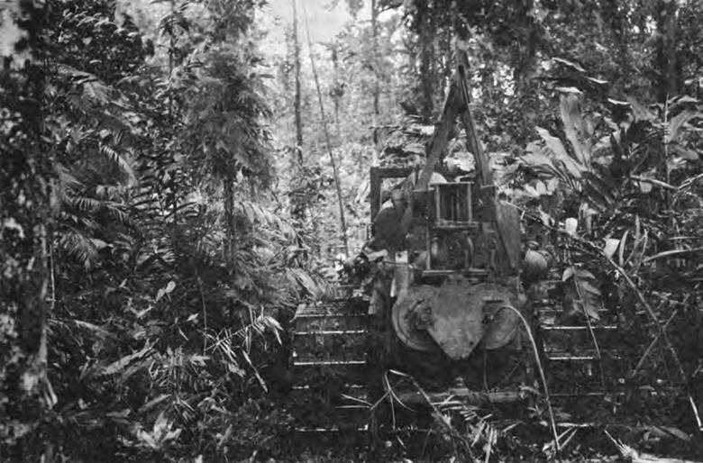
Bulldozer cutting road through jungle, New Georgia, 1943. Vehicle is a tractor with bulldozer attachment
Looming ahead was the greatest amphibious operation ever undertaken—the cross-Channel attack. The Dieppe raid of August 1942 served to point up the serious consequences of failure to overcome obstacles placed on the beaches and in the surf. In December 1942 Hoel had returned from England full of information about what happened at Dieppe and what the British were doing as a result. The Dieppe raiders had encountered steel spikes designed to impale landing craft, barbed wire, concrete walls and blocks, antitank ditches, and mines—all covered by persistent enemy fire. The casualty rate among engineers had been extremely high. To make certain that future invading forces would be equipped and trained to gain the beachhead without excessive losses, the British had constructed an elaborate beach obstacle course and had assigned high priority to the development of special armored vehicles.
Shortly after his return to the United States, Hoel recommended that the Corps of Engineers sponsor a similar investigation. Army Ground Forces gave its approval in February 1943, suggesting coordination with its own Amphibious Training Center, the Engineer Amphibian Command, and the Amphibious Force, Atlantic Fleet. The assumption of all amphibious training by the Navy a few months later removed the first two organizations from the picture, but the Amphibious Force, Atlantic Fleet, worked closely with the Engineers throughout the course of their experiments. To
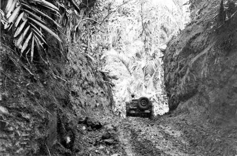
Road cut through hills and jungle is used by troops in New Georgia, July 1943
assure this coordination the Engineers selected a site near the Navy’s Amphibious Training Base at Fort Pierce, Florida. By the first of July 1943 construction of the obstacle course had progressed to a point where tests could begin. Hoel, in charge of the Fort Pierce experiments, was assigned several officers and a company of combat engineers.21
The opening of the Fort Pierce testing area coincided with the production of a tank dozer which, thanks to the unorthodox activities of Eklund and the continued interest of LeTourneau and LaPlante-Choate, exhibited every mark of a successful machine. In June 1943 funds hitherto available to the Corps of Engineers for development of the tank dozer had been cut off. The Ordnance Department was directed to assume exclusive control in this field. But Eklund,
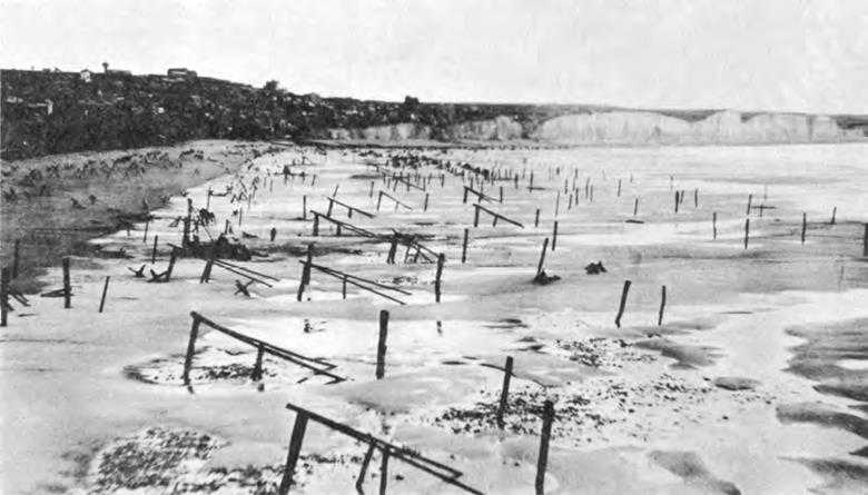
Beach and underwater obstacles, Normandy, France, 6 May 1944. Photograph was taken one month before D Day
now fully convinced that combat engineers needed a tank dozer to reduce obstacles other than mines, and that he was on the verge of obtaining one, tried and succeeded in getting the work done for nothing. He persuaded LeTourneau to construct a pilot model at no cost to the government, and shortly thereafter, LaPlante-Choate, with an eye on this competitor, followed suit.
The standards of performance set down for the tank dozer by Eklund and his civilian aide, William J. Murwin, were high. Wishing to produce a unit that could be as readily controlled as a bulldozer, they switched to a straight toothless blade.
When the LeTourneau model was tried out at Belvoir in June 1943, its earth-moving capacities were reported to compare favorably with those of a D-8 tractor. Still with no money, but even more convinced that he had something extraordinarily valuable, Eklund shipped the tank dozer to Fort Pierce, using funds available from the project for clearance of beach and underwater obstacles.22 The LeTourneau tank dozer gave an outstanding performance under a series of exhaustive tests at Pierce, easily overcoming “obstacles previously classed as rendering ‘Direct assault ... useless.’ “ In subsequent tests the performance of the LaPlante-Choate unit was equally praiseworthy.23 Procurement of a tank dozer which combined the best features of each model began immediately and the first units arrived in
Italy in plenty of time for the spring 1944 offensive. In that campaign Eisenhower recalled, the tank dozer was “a godsend.”24
Sturdevant had been watching the work at Pierce with much interest, and early in August directed the Engineer School to take advantage of the setup there to test techniques and doctrine and to bring tactical considerations to bear upon the board’s work. The school assigned Lt. Col. James E. Walsh to Pierce. Walsh stressed the fact that, unless American doctrine were changed, the infantry would precede the arrival of tanks by several waves. The infantry must be prepared to surmount obstacles using simple expedients such as wire cutters and ramps. Any large-scale use of explosives at this stage would result in heavy casualties among friendly troops. Wide gaps through obstacles need not be provided until the tanks landed. Neither could they be provided until the infantry had silenced the enemy’s fire. Nevertheless Walsh believed that much profit could be expected from further investigation of hand-placed charges and from the study of the effectiveness of rockets. And, since rockets appeared from the preliminary work at Pierce to show so much promise, Walsh encouraged Hoel’s group in its efforts to develop an engineer armored vehicle equipped with a rocket launcher.25
During the succeeding months formulas and methods for placing charges by hand were improved upon. On the assumption that air and naval activity would precede an amphibious landing, the Fort Pierce group, with the cooperation of the Navy, and while host to many observers from the Army and Navy, tested the effectiveness of various bombs and projectiles against various types of obstacles, reporting their conclusions monthly to the Engineer Board. Encouraged by the successful tests of the tank dozer, Hoel and his assistants persisted in developing a more versatile engineer armored vehicle.26
Both the projected engineer armored vehicle and the tank dozer were special purpose machines. The work power of the tank dozer was not nearly so great as that of the standard tractor-mounted dozer. The tank dozer was difficult to maneuver and subject to more frequent breakdowns. A disadvantage of the standard tractor-mounted machines, on the other hand, was vulnerability. There were many occasions, as reports from overseas showed, when operators of bulldozers and other construction machinery required protection from small arms fire, even though they did not need a tank gun. Because of this, and also because it was doubtful whether or not medium tanks would be shipped to the Pacific, the Engineers designed armored cabs for tractors and other construction machinery at the same time they were developing the tank dozer.
Lt. Col. Grant E. Beverly of the board’s Mechanical Equipment Section, and his civilian aides, George Weidner, James A. Cobb, and Miller L. Coe concluded from the outset that for advice they should lean heavily upon both the Ordnance
Department and the Caterpillar Tractor Company. The experts on armor plate and on the ballistic effects of various details of design were to be found in the Ordnance Department. The manufacturers themselves were the ones most familiar with the dimensions and strengths of their products and would be most likely to offer good advice about the effect of proposed changes.
The aim was to afford maximum protection to operators while preserving the efficiency of the machines. At either extreme these objectives were incompatible. The heavier its weight, the more rounded its silhouette, the fewer its openings, the greater the protection; the lighter its weight and the greater the visibility achieved by portholes and angular construction, the greater its efficiency. Sacrifices had to be made on both sides. The half-inch armor plate chosen was the thickest it was possible to adopt without overloading the machine, yet this plate would not withstand the normal impact of ammunition larger than .30-caliber at 2,300 feet per second velocity, and even this amount of protection resulted in some loss of efficiency in operation. The silhouette of the armored cabs was quite angular; otherwise operators could not have performed their work. The cabs were designed to facilitate assembly in the field with standard tools.
The Engineer Board, with the invaluable assistance of Ordnance and Caterpillar, completed this investigation less than three months after it was assigned. It was many more months before the Pacific theaters received any armored cabs from the United States. Engineer troops continued to improvise shields when necessary. But for the most part, the strategy employed during the early months of 1944 relieved bulldozer operators of the dangers to which they had hitherto been exposed. During this period MacArthur’s command concentrated upon capturing island steppingstones where the Japanese were least strongly entrenched. American task forces were composed of fewer men, and troops did not attempt to penetrate far into the interior so that less road building was required. An armored bulldozer sent from the States was used effectively on Morotai beach in September 1944. More were available for the Philippines campaign, where they were used in the extensive road building in northern Luzon. In Europe, armored bulldozers were considered a mixed blessing. The operator was protected from small arms fire but might because of confinement in the cab, receive severe head injuries if he struck a mine.27
Provision of armor for bulldozers and the development of the tank dozer had been a detour around the problem of mine field clearance, which was still awaiting a satisfactory solution in the fall of 1943. Meeting on 6 October of that year, representatives of the General Staff, ASF, AGF, the Canadian Army Technical Development Board, the Ordnance Department, and the Corps of Engineers agreed that all the devices tried so far were either too heavy, too complicated to project into a mine field, too slow, or too lacking in dependability. The Armco-type snake and the Aunt Jemima, the latter a disk roller device developed by Ordnance, were merely the best of the group—not a real solution. Pressure to provide something better in the way of detection as well as clearance increased early in 1944 as the Allies,
pushing north in Italy, encountered the ultimate in German ingenuity in the use of mines and booby traps. The portable mine detector, SCR 625, had performed well in North Africa but proved unreliable in Italy, first, because the soil contained so much iron, and second, because the Germans planted many more antipersonnel mines there than they had in Africa, and some of these mines contained little metal.28
These defects in performance served to emphasize the other shortcomings of SCR 625. Operators tired quickly while sweeping an arc with an instrument weighing seven and a half pounds. Often when it was most needed, SCR 625 broke down. Most failures occurred during rainy weather, but the delicate construction of tubes, transformers, and other parts accounted for a good share of them. Since operators had to stand while using SCR 625, they were exposed to fire during daylight and at night found it impossible to locate the trip wires of antipersonnel mines which had to be felt for. Under the supervision of Maj. George A. Rote, the Engineer Board investigated four different devices—a vehicular-mounted detector, a detector for nonmetallic mines, a combination metallic and nonmetallic detector, and a detector with a shortened arm.29
Development of a detector mounted on a vehicle had begun in December 1941, following a request from the Armored Force Board. For the first two months the Engineer Board experimented with the same type of circuit used in SCR 625, but in February 1942 the board learned that J. G. Doll and Maurice Lebourg, two former lieutenants in the French Army now in the States, had been working on a vehicular detector at the time France capitulated and had completed a pilot model. The detection mechanism of this unit consisting of four electronic induction bridges, was mounted seven feet in front of the vehicle. The indicating mechanism consisted of dial lights, which registered when the detecting mechanism passed over a mine, at which point the vehicle automatically braked. Impressed with the possibilities of the Doll-Lebourg model representatives of the Armored Force Board recommended mounting it on a jeep. The details of such a mounting proved complicated and time-consuming because the boom was too heavy for the light vehicle from which it was controlled. Efforts to design a lighter boom for the Doll-Lebourg device continued over the next few months, but as an alternative Rote experimented with another device, which came to be known as the prairie dog. The prairie dog consisted of a light-wheeled tractor, trailed by a detector unit controlled by a half-track. Its detecting system was similar to that of the Doll-Lebourg unit.
Spurred on in the spring of 1943 by requests from the North African theater for a vehicular-mounted detector, Rote arranged a demonstration so that a choice between
the two units could be made. The Doll-Lebourg model, called AN/VRS-1, was selected, for although the prairie dog swept a wider path and could be operated 100 feet ahead of the control vehicle—an advantage which eliminated the necessity for an automatic braking system—it was more complicated to maneuver and maintain, was extremely vulnerable to fire, and would be costlier and more difficult to produce.
Another year elapsed before any AN/VRS-1 detectors arrived overseas. In service tests at the Desert Warfare Board early in 1944, the AN/VRS-1 gave some false readings over magnetic types of soil so that procurement in quantity was held up pending alterations which eliminated this defect. Production of the first fifty sets did not begin until a month before D Day and it was fall before any arrived in Europe.
Even had vehicular detectors been available sooner and in greater quantity, their usefulness would have been as sharply limited as was that of SCR 625 because of the Germans’ gradual approach toward a completely nonmetallic mine. Fully aware of the urgent need for an instrument to detect nonmetallic mines, the Engineer Board was equally aware of the difficulties of developing one. Wishing to spare its staff from spending time in what it anticipated would be fairly long-drawn-out preliminary research, the board sought the help of the National Defense Research Committee in January 1943. During the next six months, Rote, in cooperation with NDRC, encouraged investigations which attempted to detect the presence of mines by comparative measurements of electric current, sound, or solidity. None of these was outstandingly effective, reported Rote on 1 February 1944. With the exception of the electronics instrument developed by the Radio Corporation of America, which registered the presence of a solid object, all methods were generally dependent upon dissymmetry in the ground.30 The RCA device operated with fair success over relatively nonconductive soils. But it could not be relied upon to pick out mines buried in highly conductive soils, and it also lacked the ruggedness desirable in military equipment. Yet so urgent was the demand that in January 1944 representatives of the interested arms and services recommended its procurement as AN/PRS-1. Overseas, the performance of AN/PRS-1 was more of a disappointment than had been anticipated. It was very heavy—19 pounds. Only after a great deal of experience could operators distinguish between live mines and rocks or roots. AN/PRS-1 was not designed to handle the small antipersonnel mines that were sown in such great numbers by the Germans. Efforts to improve this detector and to evolve other means of detecting nonmetallic mines continued, but none had been developed to the point of procurement by V-J Day. Similar results marked attempts to develop an instrument capable of detecting both metallic and nonmetallic mines. Although some devices showed promise, victory was achieved before pilot models were produced.31
Faced with the failure to develop a detector capable of registering the presence of antipersonnel mines, AGF, in June 1944, proposed something of a compromise.
Reasoning that simplifying the location of the trip wires so often attached to these mines would greatly increase the safety of the soldier searching a mine field, AGF suggested the development of a detector that could be used while kneeling or lying flat and which would permit one hand to be free to search for such wires. Accepting wholeheartedly the need to supply something of the sort at once, the Engineer Board plunged into the work of modifying SCR 625 as the quickest means of accomplishing the purpose. At the same time the board took advantage of the opportunity afforded by this opening of the subject to propose a complete redesign of SCR 625 in order to make it lighter, more rugged, and waterproof.
In pursuit of the board’s first aim, that of modifying SCR 625, Rote got in touch with representatives of the Horni Signal Manufacturing Corporation, one of its producers, which made the desired changes. The amplifier and search coil were retained in the new model. A short rod for operation in a prone or kneeling position could be connected to a longer one for operation while standing. With a view toward lightening the instrument, the visual indicating meter (never very dependable) was eliminated, making it possible to attach the control box to the operator’s belt rather than to the instrument’s rod, and making detection completely dependent on aural controls. The new set thus produced, the SCR 625(H), while maintaining a standard of performance equal to SCR 625, was four pounds lighter, yet so slight were the differences between the two that one could be converted into the other in the field upon receipt of a kit containing the new parts. Early in October 1944, the Engineer Board recommended that procurement of conversion kits as well as of complete units of the modified detector begin, but because of the dissatisfaction of the Signal Corps with the drawings and specifications furnished, no units were ordered until January 1945. As a result, few arrived overseas in time to be of service.
The best detector developed—the redesigned SCR 625 which the International Detrola Corporation agreed to work on in August 1944—never got overseas at all. Utilizing the same principles of operation as those of SCR 625, Detrola’s design engineers and Rote and his assistants produced a unit, AN/PRS-3, that (1) could be operated in a prone, kneeling, or standing position; (2) was more than ten pounds lighter; (3) was more ruggedly constructed; (4) was waterproof; and (5) was more efficient in detecting antipersonnel mines. While not all that could have been wished for, since the problem of detecting nonmetallic mines remained unsolved, AN/PRS-3 thus overcame many of the deficiencies of SCR 625. Recognizing this fact, representatives of AGF, Signal Corps, NDRC, OSW, and Engineers agreed early in January 1945 to switch to procurement of this type. Orders were canceled after V-E Day, however, because supplies of SCR 625 were sufficient to meet the needs of the Pacific theaters, where mines were never extensively employed.32
Although detectors were the first step, if not the key, to clearance of mine fields, and thus failure to produce anything approaching a foolproof detecting instrument went a long way toward spelling lack of success in
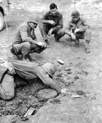
Soldier removing an enemy mine, North Africa, April 1943
this effort, development of more efficient means of clearing paths through mine fields might have made up somewhat for detection failures. For this reason, in February 1944 Army Ground Forces urged the Engineers to conduct an all-out drive to provide something superior to the snake. In reply the Engineers requested a better testing area and the assurance of sufficient personnel. Army Ground Forces offered space at the A. P. Hill Military Reservation, not far from Belvoir. But it was June before all details had been straightened out, and even after that the Engineer Board experienced difficulty keeping enough troops on hand to carry on its program.33 In the months that followed, the group at A. P. Hill tested more than twenty-five different devices such as detonating cord, plywood and neoprene rollers, fiberglass neoprene-coated hose filled with liquid explosive, and carpet roll torpedoes. In addition, Ordnance, at the suggestion of the Engineers, developed a means of launching rockets from a trailer towed behind a tank.34
Despite these intensive efforts, the Engineers failed to develop any clearing device which they considered superior to the snake. The snake, to be sure, could be depended upon to clear a lane through a mine field. But on the edge of the path, so troops in the ETO discovered, there remained mines that had been affected although not detonated by the snake’s blast. These “tender” mines were the source of potential casualties, yet were extremely dangerous to remove. Bangalore torpedoes had the same tenderizing effect. The Ordnance Department, under great pressure to provide something, sent thirty scorpions overseas in the spring of 1943. They were discarded as useless by engineer troops in Italy. The driven-disk exploders which Ordnance provided later were little, if any, better. They had a tendency to bridge the mine, were not mechanically dependable, and were heavy and slow. Engineer troops operating in western Europe preferred the scorpion. In the end most mines were discovered and removed by soldiers, crawling on hands and knees and equipped
only with probes, and the tank dozer remained the combat engineers’ closest approach to an assault vehicle.35
The engineer armored vehicle designed at Fort Pierce was an elaboration of the tank dozer, basically “a medium tank with some of the guts removed, with doors on the sides, and a dozer blade.”36 A rocket launcher was substituted for the standard 75-mm. gun. A trailer, or pallet, for carrying extra demolitions could be attached at the rear of the vehicle, a snake at its front. On its blade could be carried a doozit, a device for placing explosives mechanically. All of these accessories possessed limitations. Those of the snake were well known. The rocket launcher had to be brought quite close to the target in order to assure accuracy. Both the launcher and the doozit were extremely vulnerable to fire. Yet the Engineer School’s representative at Pierce, at the time the engineer armored vehicle was tested in the spring of 1944, believed that, with its accessories, the vehicle added up to a reasonably efficient piece of equipment which afforded good protection to its operator.37
The most formidable block in the way of getting the engineer armored vehicle adopted was the organization and doctrine of the American Army. When the Engineers cast about for a place to assign this specialized piece of equipment, they were forced to conclude that the armored battalion was the only unit that could absorb it. Undaunted, Engineer School and Board joined in recommending that “consideration ... be given to the forming of special Engineer units to exploit the apparently excellent possibilities of this multi-purpose weapon.’’ To back up their position they appealed to British practice. The British had such a vehicle and had organized special assault brigades around it.38 General Worsham, chief of OCE’s War Plans Division, expressed no enthusiasm for this idea. “I can’t quite see forming a new organization to fit a particular vehicle,” he remarked at a staff meeting. “A vehicle of this kind would be useful to many types of engineers if they are attacking a fortified place, not only beachheads.” Worsham wondered why the vehicle could not be issued as the tactical situation demanded. It could not, he was advised, because operators would have to be specially trained to handle it. Worsham was impatient. “You would never get any place,” he closed the subject, “establishing a new organization to employ one implement of war.”39 These arguments turned out to be largely academic. Engineer armored vehicles were not developed in time to be issued to units participating in the cross-Channel attack, where they might have been employed to greatest effect.40 For this operation, combat engineers were to have been supplied with tank dozers, in addition to wire-cutters and explosives.
Unfortunately, of the sixteen tank dozers assigned to combat engineers in the Normandy landings at OMAHA beach, only six were delivered ashore and one of these with its blade missing. Most of the tank
dozers—like the amphibious tanks which Bradley planned to land ahead of the infantry—sank in the stormy waters of the Channel. Although naval support proved invaluable as the battle progressed, initial air and naval bombardment were quite ineffective. German resistance was unexpectedly heavy. These adverse circumstances and the crowding of friendly troops on the beach made it impossible for the engineers to open exits through the obstacles as scheduled. Tasks that had called for courage now demanded heroism. Engineer casualties reached 40 percent on D Day on OMAHA. More tank dozers would have served the engineers in good stead. Certainly the German defenders had great respect for these vehicles, singling them out as prime targets and succeeding in knocking out all but one.41 The tank dozer was, however, only moderately effective against the hedgerows of Normandy. For the specific purpose of overcoming these obstacles, a tank sergeant invented the highly efficient hedge-cutter, a toothed blade for attachment to the tank. After the break-through the tank dozer continued to serve as it had in Italy. Issued to armored as well as engineer units, it combined the fire power of a military weapon with the work power of an industrial machine, and as such was the fighting tool par excellence of the combat engineer.42
At least one foreign writer has criticized the American Army for failing to follow the British lead in adopting more specialized armored vehicles. This writer claims that the crabs, an improved scorpion, which plunged ahead flailing away at mines, and the AVREs (Assault Vehicles Royal Engineers), which threw their peculiar charges at pillboxes and walls, turned the trick on the British sectors of the beaches despite the fact that these vehicles were quickly knocked out by the Germans. Hoel also remained convinced that the authorities placed too much emphasis upon perfection. Hoel and his followers would have settled for a device that could clear out sufficient mines to get a large percentage of vehicles through.43
Reflecting on the failure to put a really effective mine detector in the field, a member of the NDRC laid most of the blame on weaknesses in the “system”—inadequate facilities for testing, poor coordination between research agencies, and failure to arrive at an understanding of precisely what was required under what conditions.44 The same could have been said for the system employed to develop mine clearing devices. In both areas, many persons, within and without the military establishment, working at widely separated localities, were involved. Meeting together, exchanging visits, corresponding, although undertaken with the utmost good will, could not compensate for the lack of an over-all coordinated program. Yet while more efficient organization would doubtless have been beneficial, it would not have assured success. Dealing with land mines, which were used extensively for the first time in World War II, was an extremely complicated matter. The difficulties inherent in the undertaking, in combination
with the late start of the investigation as a whole, in all probability had a greater determining effect upon the outcome than the scattering of responsibility. There was, moreover, for better or worse, the practice, somewhat modified as the war progressed, of relying primarily upon the infantryman in the initial assault. This doctrine was undoubtedly responsible for the late start in developing mechanical clearing devices, and doubtless had a retarding effect upon the investigations once they were started.
Bridging
The investigations into bridging equipment were in striking contrast to those in the field of mine detection and clearance. Responsibility was centralized. Experience was long and continuing. In the months immediately following the declaration of war the specter of increasing weights which had previously haunted the Engineers seemed to have disappeared. In February 1942, the Ordnance Department stated that the Army’s main reliance was still on the Sherman tank, in the 30-ton class. Production of a tank in the 35- to 40-ton class, while under study, was so remote a possibility as not to “warrant any change in the procurement planning ... for bridging equipment.”45 Although Besson, now chief of the Development Branch, OCE, expressed some mistrust of this statement, the Engineers planned no revision in their program but concentrated instead upon perfecting the floating equipage designed for 30-ton loads, namely, the 25-ton ponton and steel treadway bridges.46
The Sherman tank had crossed the treadway bridge successfully on several occasions, but no measurement of stress had been made. The Engineer Board felt, therefore, that not enough was known about this bridge. In April 1942 Howard H. Mullins, the board’s senior engineer for bridge design, supervised the accumulation of such data in a series of tests on the Chattahoochee River. His measurements reinforced the conclusions arrived at previously: the bridge was safe for the passage of 30-ton tanks, provided the drivers maintained a 100-foot distance between them.47
Armored Force engineers, proud and enthusiastic about the treadway bridge itself, were completely dissatisfied with the bridge truck on which the rapid erection of the bridge was so dependent. The truck was designed to carry out the two operations of transporting and unloading the treadways onto the floats. It had been developed during the summer of 1941 by the Four Wheel Drive (FWD) Auto Company under the direction of the Engineer Board. The device for handling the treadways was attached to a bumper at the front of the truck and, when not in use, extended back over the cab and almost the length of the truck. When erected it formed a tripod, or A-frame, which supported a single hoist controlled by cables. Similar to the devices used by telephone companies for unloading poles, it lacked the rigid control necessary to handle the bulky treadways with economy of manpower and safety to men and equipment. Its operation was very slow: it took from five to fifteen minutes to place the handling device in position, and roughly another fifteen minutes
to place each length of treadway on the floats.48
After the Carolina maneuvers in the fall of 1941, Stanley called on Cowley to work out something that would be powerful enough to remove two treadways from the truck at one time in five minutes. The result was the so-called “bullwheel” device, which consisted of two parallel arms mounted on the rear of the truck and joined by a cross member to which chain hoists were attached. The unit was controlled by means of a gear-operated power take-off. Stanley asked the board to investigate the bullwheel device in September 1941 and the board in turn forwarded the idea to the FWD Company for an opinion, with the proviso that the A-frame trucks already ordered were to have priority. What with the rush of work on the original order no more than a preliminary drawing had been made by January 1942.
Late that same month Capt. Frederick J. Bogardus went to Fort Knox to review the status of the bridge truck. The best anyone could say for the A-frame gear was that it was “better than nothing.” Procurement should continue only until the bullwheel lift had been perfected. Toward this end Bogardus and Cowley applied themselves, making sketches and even cardboard models, until they concluded that hydraulic controls would offer great advantages over the gears which regulated the mechanism as then designed. No winches would be necessary if this change turned out to be practicable and the entire operation was bound to be speeded up. The following week the “ideal” bridge truck was described to Herbert O. Day of the Daybrook Hydraulic Corporation. Daybrook produced a design which struck Bogardus’ assistant, Glenn D. Ferguson, as having “considerable merit.” It did. The hydraulic ram produced by Daybrook could lift three connected treadways (approximately forty-five feet) at once. Time consumed in pickup and laying was one and a half minutes. The hydraulic lifting device provided a link between the treadway bridge and its transportation which was not present in any other bridge.49
Provision of an efficient bridge truck served to heighten the enthusiasm for the steel treadway bridge within the Armored Force. But AGF and the Corps of Engineers continued to regard it as specialized equipage. Nothing had occurred to call into question the reasoning that lay behind their preference for the 25-ton ponton bridge for infantry units. Infantry did not require a bridge that could be constructed as rapidly as the treadway, particularly at the addition of so much cost and at the sacrifice of so much ruggedness. But it had been made clear from a series of tests, begun in the fall of 1941, that the 25-ton ponton equipage would have to be strengthened in order to carry the Sherman tank. The addition of standard pontons would provide the desired increase in capacity, but would also add considerably to the already long bridge train. The board adopted instead 12-ton pneumatic floats, placing one in each span. Thus reinforced, and with practically no increase in transportation, the bridge safely supported 40 tons. The Engineers showed
Bridge truck with hydraulic lifting device. This device could lift three connected treadways at one time providing a link between the treadway bridge and its transportation
no concern about the fact that construction time was lengthened for they did not expect to reinforce most of these bridges. Tanks would not always be present.50
As tests on the 25-ton ponton bridge were being completed, news came in that American engineers in the British Isles who were taking part in planning the invasion of the Continent (then scheduled for the spring of 1943) might prefer the floating Bailey.51 Although such a choice seemed logical in view of the serious shortage of cargo space, Besson warned AGF against a hasty decision:
My tour of duty in England last summer taught me that the British are overly optimistic, not only on the capabilities of their own equipment but also in their production planning. They are prone to seize admitted advantages and extrapolate unwarranted conclusions with a complete disregard for various disadvantages. Based on my observation, I strongly recommend against complete reliance upon the British to meet all of our bridge requirements.52
Any such decision should await “an analysis of capacity, transportation and
construction.”53 The Engineer Board on 9 July 1942 was asked to make such an analysis, comparing the Bailey’s performance to that of standard American bridges.54
In August, Besson and Capt. George W. Howard of the board’s bridging section went to London, where they found Col. Frank O. Bowman, Engineer, II Corps, not nearly so enthusiastic about the Bailey bridge as they had expected him to be. Reporting to his chief, Maj. Clayton E. Mullins, on 10 August, Howard noted “that the 25-ton ponton equipage still is very much in evidence. Frank’s [Besson’s] worries have now changed from the fact that they would not use the equipment to whether so much equipment should be allotted to this Theater.”55 Bowman granted the superiority of the fixed Bailey for construction in rear areas where time was not of so much consequence. He would eliminate the H-10 bridge because it would have to be shipped in. He wished to retain the 25-ton ponton as a tactical bridge because it could be constructed more rapidly than the floating Bailey. Agreeing wholeheartedly with Bowman that the Bailey’s usefulness was confined to rear locations, Besson argued for inclusion of the H-10 bridge and succeeded in setting up requirements for a few units. As the final recommendations stood when Besson left England, the Bailey, instead of replacing all American medium and heavy bridging, had replaced only the H-20.
Again with an eye on savings in shipping space, Bowman proposed to substitute pneumatic floats for 10-ton pontons. Assault boats and pneumatic floats for ferrying troops and vehicles of 8 tons and under would carry the first waves across the river. Division troops would then build the 12-ton capacity pneumatic (infantry support) bridge, and following this, Corps troops would construct either a trestle bridge or a pneumatic floating bridge with trestle balk to carry 18-ton loads. Substitution of floats for 10-ton pontons had been under consideration in Washington since early summer, and in September the board concluded that this move was desirable. The bridge thus evolved was composed of the standard 10-ton superstructure mounted on 12-ton floats. It replaced not only the 10-ton ponton but also the infantry support bridge and the special motorized battalion bridge.56
By the fall of 1942 the Engineers were, if anything, oversupplied with bridges. This situation was in process of being corrected when the storm broke. In the course of five weeks, beginning in mid-September, four serious accidents occurred while tanks were crossing the treadway bridge. Hard upon these disasters came news that tanks would become both heavier and wider.
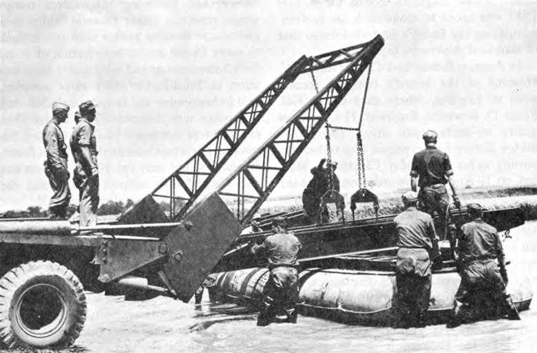
The first accident on the treadway bridge took place at the Desert Training Center where the 2 2nd Engineer Armored Battalion of the 5th Armored Division was training.
The bridge spanned the turbulent Colorado River from the California to the Arizona border. A medium tank was almost across on its return trip to the California side when its treads began to climb the curb. The bridge tipped, the tank fell on its side into the water, and three floats slid out from under the bridge. No lives were lost. The second accident took place at Fort Benning on the Chattahoochee, again in a swift current. The commanding officer was experimenting with distances between tanks. When the distance was cut to 20 yards, the floats submerged and the bridge twisted, causing two floats to slide out. Again no lives were lost but one tank was submerged in the process of towing it to shore. During maneuvers in Tennessee the third accident occurred, on a bridge across the Cumberland River constructed by the 24th Engineer Armored Battalion of the 4th Armored Division. Most of the 37th Armored Regiment had crossed when one tank driver stopped and another closed in to a distance of about 15 yards. This section of the bridge then submerged, twisted counterclockwise, and released five or six floats. Both tanks were thrown into the water. Six men drowned.57
The fourth accident took place at the same site as the first during tests to determine the cause of the others. It was described by Major Mullins who was in charge of the tests:
The right track of the tank was held against the right (downstream) curb throughout the test [according to instructions]. At no time did the tank treads climb the curbs. ... The fourth or fifth float was the first to be submerged. At the seventh or eighth float, it was noted that these floats were submerged two to three inches, with the water running up on the saddles. At about the 13th or 14th float, the water was completely over the saddle structure and was touching the bottoms of the treadways. The bridge, at this time, appeared level. Shortly thereafter, when the tank was on the 17th or 18th treadway, the bridge developed a slight list toward the upstream side. This list seemed to be caused by the downward forces created by the tension in the anchor cables and the current piling up on the upstream side of the saddles and floats. At this point, the driver was instructed to accelerate his tank to see whether or not the list could be lessened or held static. At about the 19th treadway, it was apparent that the list was gradually increasing. At this moment, the driver was instructed to leave the tank. The driver came forward approximately one-half to one treadway length further and brought his tank to a stop, at which time he was ordered to leave the tank immediately. The driver was either caught or restrained from leaving the tank and made at least three efforts to come out the open driver’s hatch. He was almost completely out by the time the tank entered the water but he was not seen thereafter.58
A wave of concern spread through OCE, the Engineer Board, the Armored Force, and Army Ground Forces as news of the four accidents came in. But Armored Engineers clung to their bridge. Typical of their reaction was that of Col. Bruce C. Clarke who had been one of the first to complain
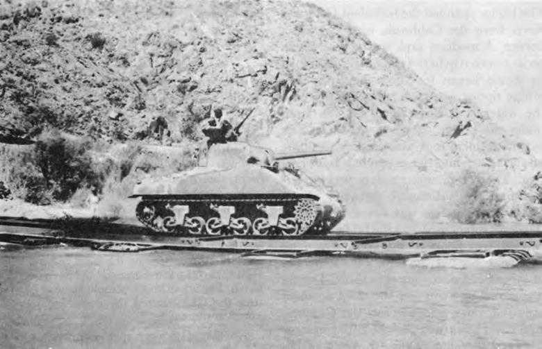
Medium tank crossing treadway bridge over the Colorado River, 17 September 1942. A few minutes later the vehicle fell into the river
about the standard bridging and who had initiated some of the early experiments at Fort Knox. Clarke, at this time commanding the 24th Engineer Armored Battalion which had been associated with the most serious accident, blamed the disaster entirely on personal error.59 His opposition to attempts to make the bridge foolproof were strongly endorsed by his commanding officer, Maj. Gen. John S. Wood: This ... bridge has been crossed many times by the 4th Armored Division with all types of vehicles. It is possible that redesign or additional attachments may lessen the probabilities of accidents. However, it must be realized that additions to the bridge will add materially to the amount of transportation necessary ... and the time necessary to construct it. Any increases of this kind will lessen the many advantages now possessed by this bridge over other types.60
Typical of Washington’s reaction was that of Lt. Col. Paul W. Thompson, then executive assistant of the Troops Division, who wrote Sturdevant immediately after the first accident:
“It underlines the fact that we have adopted and issued a bridge which is essentially untested. ... There is no time for recrimination, but the present instance illustrates the pitfalls which seem invariably
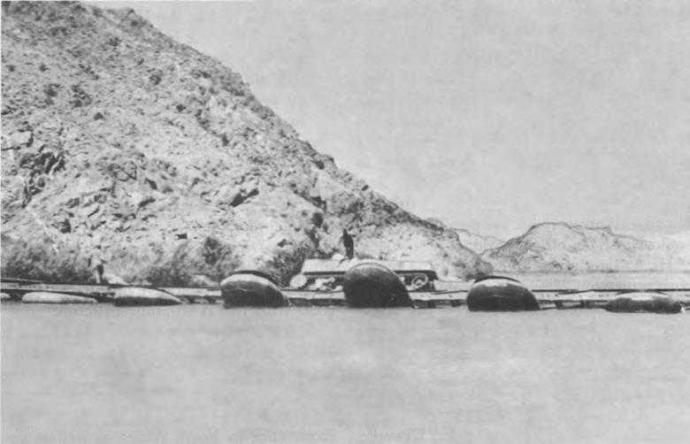
Tank falling into the Colorado river after its treads climbed the curb, tipping the bridge. Note three floats sliding out from under the bridge
to develop when a tried and true item of equipment (i.e., the 25-ton ponton bridge) is supplemented by an item which looks so good at first glance.”61
But neither Thompson nor anyone else proposed to discard the bridge. The accidents had revealed some weaknesses. Systematic tests might reveal more. After the facts were in, these weaknesses could probably be corrected. Responsibility for conducting the engineering phase of the tests was assigned to Major Mullins; that for the service tests to the Ground Engineer of AGF, with the Armored Force Engineer to maintain close liaison. The site chosen was a side channel of the Colorado River extending downstream from a sluice gate of the Laguna Dam in Arizona—an ideal spot because currents could be changed by operation of the dam’s gate. Mullins began his tests on 23 October and ended them on 16 December.
The most obvious weakness which the accidents had revealed in the treadway bridge was its lack of buoyancy. Whatever the initial cause or combinations of causes—climbing of the curbs, tanks following each other too closely, panicky drivers, or swift current—some floats were submerged and subsequently were torn out from the bridge in all four accidents. Mullins’ primary aim therefore was to provide sufficient buoyancy, but he wished also to provide other safeguards. By 25 November he could report
that a 17- to 18-ton float, 31 or 32 feet long (as against the 12-ton, 15-foot float of the original design) with upraked ends seemed safe for loads of 33 to 34 tons. Less progress had been made in designing a protective curb for the treadways—4 inches additional height would make it difficult but not impossible for the tank to climb out. Mullins thought the best answer to the climbing problem lay in better training of drivers. Human errors were always possible. A tank could be driven off any bridge.
He had not given up on supplying better curb protection, however, and shortly thereafter Lt. Richard R. Stander of the Engineer Board devised a 1¼-inch round drill rod, welded on top of the treadway and projecting about ⅛ of an inch inward. This proved highly efficient in preventing the tank treads from mounting the treadway. At the same time, 1st Lt. Gordon Gravelle conducted various experiments with lights and markers, with the result that traffic crossing the bridge was safely speeded up. These three improvements transformed the steel treadway bridge into a safe structure without sacrificing any of its efficiency.62
This conclusion was reached just about the same time that the board was considering the results of comparative tests of the Bailey with the standard H-10 and H-20 bridges. The great advantage of the Bailey bridge, Howard pointed out, lay in its flexibility as regards capacities and spans, but its many parts made for slower construction and more transportation. A minor disadvantage of the Bailey was the fact that it could not be readily widened as could the H-10 and H-20. The Troops Division, OCE, had assured the board, however, that widths of vehicles would be held to the limit the Bailey could accommodate. In his presentation to the Engineer Board, Howard recommended that the H-10 bridge be retained and that the H-20 be retained in all but the European theater. With Thompson arguing strongly for the adoption of the Bailey and Crawford insisting that it had not as yet been thoroughly tested, the board was unable to come to a definite conclusion. Its tentative recommendations submitted to OCE on 12 December 1942 were that the H-10 be retained and the Bailey be procured in place of the H-20 for all theaters. Decision as to the use of the Bailey superstructure as a heavy ponton bridge should await comparative tests in swift currents with the H-10 superstructure.
A few weeks later what had seemed a minor disadvantage in the Bailey assumed rather serious proportions, and so far as the treadway bridge was concerned raised even more serious questions as to its suitability. Experience in North Africa as well as observation of the trends in foreign armies gave rise to complaints about the capabilities of the Sherman tank. The American Army needed a tank with greater fire power, greater maneuverability, greater speed, and greater crew protection. While the Corps of Engineers, through participation in the
Ordnance Department’s Technical Committee, was aware of this need and of the conviction in Ordnance that it could be met only by providing a heavier, wider tank, the Engineers were also aware that AGF headquarters had not favored the development of heavy tanks in the past. The Corps professed surprise if not shock, therefore, when Ordnance announced in January 1943 that the new medium tanks of the M-4 series would be 114 inches wide; the T20, 122 inches; and the T23, 124 inches, as compared with the 96-inch limit prescribed by the formal Army regulation and the actual 99-inch already present in the Sherman tank. Ceilings on weights would also be lifted somewhat to 17 or 18 tons for infantry divisional vehicles and to 35 or 40 tons for armored divisional and army vehicles.63
These increases in weights and widths would affect every bridge on the books. The M-3 pneumatic ponton bridge would have to be reinforced and widened before it could pass 18-ton divisional loads and even then traffic would be required to proceed at a slow rate of speed. The 25-ton ponton bridge was wide enough, but the amount of reinforcement necessary to provide a normal capacity of 35 tons made its use questionable. The steel treadway bridge was much too narrow, having two 33-inch treads on a total width of 106 inches. The introduction of wider tanks would necessitate widening the treadways themselves—not simply spacing them farther apart—because the inner edges of the treadways would need to be near enough to accommodate trucks and other vehicles. Longer and heavier chess would be required for the H-10 and H-20 bridges. The Bailey bridge came closest to being adequate. Its capacity could be readily increased, and with a clear deck of 129 inches, was wide enough, if only barely so. Provision of a guard rail should give sufficient guidance for drivers. The Engineers were not greatly worried about modifications in design. These could be accomplished with relative ease. Their most serious concern was the fact that quantities of bridging equipment in stock would be obsolete and that it would take months for procurement to catch up with the new requirements.64
Much as they deplored the changes announced by Ordnance, the Engineers saw neither hope nor justification in opposing them. The limitations formally prescribed, and in many cases already exceeded, were obviously too restrictive. What the Engineers did want, Reybold informed Somervell, was a quick decision and some protection against sudden revisions in the future. But revision of regulations should be undertaken at the same time that new designs were proposed so that the Corps of Engineers could prepare for the change. To insure that this was done Reybold recommended that a committee composed of representatives of the General Staff, Army Ground Forces,
Army Air Forces, Ordnance, and Engineers be placed in charge of revising the applicable Army regulation. Ordnance and Engineers were to maintain direct and continuous liaison “with a view to keeping the design of development models within the capacity of bridges in quantity production and, when this is impracticable, to enable the Engineers to work out modifications in the bridging program which can be placed in quantity production by the time the new Ordnance equipment is produced.” The Ordnance Technical Committee was to be restrained from recommending the adoption of any equipment “unless it can be clearly shown that the bridging program ... meets, or can be modified in sufficient time to meet, the requirements which would be imposed by the proposed new equipment.”65
SOS felt the Engineers were screaming before they were hurt. Brig. Gen. Walter A. Wood, Jr., director of its Requirements Division, pointed out that the Corps was now informed of the proposals and that its comments, along with those of AGF, would be taken into account by the General Staff. Since it would take several months before the wider tanks would be produced in quantity, bridges to support them could presumably be designed.66 On 6 February, Clay turned down all three of Reybold’s suggestions. A committee was now revising the Army regulation. No standing committee was necessary. Liaison between Ordnance and Engineers could be accomplished through the already functioning Technical Committee, but the Chief of Engineers might assign a representative to the Tank-Automotive Center if he desired. The regular channels—Technical Committee, Chief of Service, Commanding General, SOS, and so on upward—were deemed sufficient to assure protection of all interests.67
While Reybold was attempting to insure the Corps against the future, Besson, Thompson, and the bridge experts at the Engineer Board were considering various means of overcoming the present crisis, among which were scrapping the treadway bridge entirely or radically changing its character by decking it over. In back of these proposals lay uncertainty as to whether American bridging would be required to carry the British Churchill (45-ton) tank or an American equivalent. The treadway bridge, even the Armored Force agreed, reached its practical limit at 35 tons.68
One thing was certain. The Armored Force still wanted the treadway. Overseas, it had already proved itself. If, moreover, a treadway bridge capable of carrying 35 tons could be developed quickly, it might be used as an argument to hold weights to this limit. By 6 February, the program included experiments with both wider treads and a
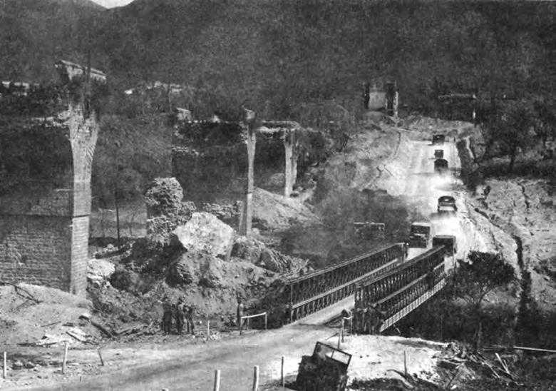
Bailey bridge over bypass on Highway 7 near Sessa Aurunca, Italy, April 1944
decked-over treadway bridge, and the design of a guardrail for the Bailey.69
The treadway bridge, M-2, designed by Col. Clayton E. Mullins, Howard H. Mullins, and assistants at the Engineer Board with the help of Cowley, was a product of the fall 1942 accidents and the demand that both the old and the new tanks be accommodated. The Armored Force did not want a completely decked bridge because of the greater time required in construction and because such a bridge could not be readily transported in the trucks already available. The desired capacity was attained in the M-2 bridge by adopting larger (33-inch wide, 33-foot long) pneumatic floats and shorter and wider (12-foot long, 45½ -inch wide) treadways. Procurement of the M-2 treadway bridge began in June 1943.70
By this time the steel guardrail which would render the Bailey bridge safe for the wider tanks had also been designed. Still partly undecided was the extent to which the Americans would follow their British
allies in adopting the Bailey as an all-purpose bridge. The tendency to do so was strong, for American engineers in the ETO were by this time fully convinced of the Bailey’s advantages. In February 1943, the Supply Division had notified the Engineer Board that the Bailey would supplant the H-10 as well as the H-20 in meeting the requirements for fixed bridging, and that should tests of the Bailey as a floating bridge prove successful, the H-10 would be dropped entirely.
The new limitations on weights and widths of vehicles were formalized on 28 August 1943. Vehicles measuring 18 feet or less between axles and assigned to infantry divisions could weigh as much as 18 tons loaded and measure 108 inches in width. In the few cases where the measurement between axles exceeded 18 feet, thus providing greater distribution of load, gross weight could slightly exceed 18 tons. Vehicles measuring 18 feet or less between axles and assigned to armored divisions or armies could weigh as much as 39 tons loaded and measure 124 inches. A greater gross weight was also allowed for those armored division and army vehicles which measured more than 18 feet between axles. The modifications made in the Bailey and steel treadway bridges made these structures safe for the increased weights and widths.71
But the Engineer Board’s success in adapting the treadway and Bailey bridges to the new requirements did not satisfy Army Ground Forces. As Headquarters, AGF, viewed the bridging equipage available to infantry units in September 1943:
... the reinforced five boat infantry support raft will ferry combat team loads up to a gross of ten tons in a stream of velocity of 3.5 miles per hour. The M-3 bridge, fully reinforced will pass eighteen ton tank loads with restricted movement in currents of velocities up to 4.8 ft. per second, but will not pass the four ton truck with trailer and bulldozer in velocities over about one mile per hour. The twenty-five ton heavy ponton bridge, when fully reinforced with metal pontons, will carry a safe load of only thirty tons with restricted movement in a stream of velocity 5 miles per hour.72
This situation, concluded AGF, demanded a complete revision in floating bridge equipage.
Wishing to depart from current dependence on a different bridge for each different set of loads, AGF specified that the new bridging components be the same for all bridges. This condition could be met, AGF suggested, through the use of half-boats—placed singly in the division bridge, joined end to end to form supports for the army bridge, and spaced closer together to carry exceptionally heavy loads. The bridge was to be fully decked and all parts light enough to be put in place by hand. Construction time for the divisional bridge was set at one-half hour plus three feet per minute; for the army bridge, two hours plus two feet per minute. These conditions could be met if both boats and balk were constructed of light metals such as aluminum, which by this time was in less critical supply and for which AGF was prepared to request AAA priority.73
Lacking sufficient staff to develop the division-army bridge as quickly as AGF desired, the Engineer Board sought the aid of civilian firms. By 4 November, the naval architects, Sparkman & Stephens of New York, had agreed to design a ponton and superstructure, and the consulting engineers, Howard, Needles, Tammen, and Burgendoff of Kansas City, to design a superstructure. Shortly thereafter the Allison Steel Company also contracted to work on a superstructure. But the five months allotted these designers to fulfill their contracts had not elapsed when requirements changed.74
On 19 February 1944, G-4 announced that allowable weights for divisions would be raised from 18 to 25 tons and for armies from 38.9 to 50 tons. The roadway of division bridges should measure 128 instead of the former 108 inches and that of army bridges 150 instead of 124. If the 25-ton ponton was approaching the obsolete before, it was clearly out of the picture now. The Engineering and Development Division urged the Engineer Board to push the division-army bridge.
There was, to be sure, an alternative—the Bailey, which, if widened, could carry the increased loads. Tests of the floating Bailey had convinced the board that it was superior to the 25-ton ponton as well as the H-10.75 Colonel Howard, in charge of testing the division-army bridge, was not impressed with the preliminary designs:
Once the Panel Bridge ... is erected, it is believed to be a better bridge, except for its width limitations, than any of the experimental bridges now being procured. ... If a means was provided to adjust the floor width of the Panel Bridge, and to lighten the members, it is believed that this type of bridge would be a much better solution to the present problem than the superstructure now proposed.76
AGF disagreed. Its representatives were pleased with the division-army bridge. Although the Engineer Board designed a Bailey bridge with a clear roadway of 150 inches, beginning this job in March and completing tests in September 1944, the Bailey was never regarded as a substitute for the division-army bridge.77
The superstructure of the division-army bridge, which followed the Sparkman & Stephens design, looked more like the 25-ton ponton bridge but was actually closer, structurally, to the treadway. It looked like the 25-ton ponton bridge because it was fully decked. It was structurally similar to the treadway because balk and chess were combined. While the “treadway” was a three-sided section which formed a channel, the “deck-balk” designed by Sparkman & Stephens had four sides. Fitted together, these hollow aluminum sections provided an articulated connecting system, and flooring as well. The components that proved most troublesome to perfect were the half-boats and the approach which spanned the distance from shore to the point where the water became deep enough to float the first ponton. By mid-August 1944, two attempts had been made and a third was under way to design a half-boat combining the desired strength and lightness. Writing from the Yuma Test Branch, Howard urged still further modifications: “It is time that it be made clear to the designers that the primary
consideration is to secure a ponton capable of carrying 50-ton loads, and secondarily, to hold the weight to a minimum,” he wrote his superior at Belvoir.78 Indeed, by this time AGF had conceded that pontons capable of supporting the load would perforce be too heavy to handle by manpower, and had therefore consented to the use of cranes for loading and unloading them.
Although the bridge was far from perfect when tested, the over-all design proved so excellent that AGF accepted it on 15 November 1944, subject to assurances that use of a stronger aluminum alloy in the balk would correct the weakness in the approach span, that the 50-ton trestle then being fabricated was satisfactory from an engineering standpoint, and that the ponton would be strengthened.79
The adjustments thus made turned out well. In December, the site for service tests was switched from the placid Sabine River in Texas to the turbulent Columbia near Rufus, Oregon, where it was found that the new bridge (now called the M-4) would support 50-ton loads in currents up to 10.4 feet per second.80 Construction time—two hours plus one foot per minute—exceeded the rate demanded by AGF.81
Getting the M-4 overseas in time to be of service was something else. One hundred and sixty-eight sets of bridges had been ordered in November 1944, but lack of materials had slowed production. The War Plans Division—worried about the impending Rhine crossing—saw no hope of any deliveries before 1 April.82
The Rhine was crossed, thanks in part to German failure to blow the bridge at Remagen, and thanks to the steel treadway bridge which American engineer troops had completed before the Remagen bridge collapsed. At the Rhine, as in so many other crossings, the treadway bridge was more than adequate for the job. With the treadway and the Bailey—both radical departures from proven designs—British and American troops kept pressing hard at the enemy’s heels. With Army Corps consisting of two infantry and one armored division and with tank battalions attached to infantry, bridging had to pass tanks at all times. By September 1944 only three reinforced 25-ton ponton bridges had been erected in the European theater. The decision to produce the Pershing tank came so late in the war that few got overseas. As it turned out, the Engineers kept abreast of Ordnance, and while in the impatience which is so often a product of anxiety to do one’s best, each service on occasion fell short of fully comprehending the other’s point of view, both succeeded in accomplishing the job in a satisfactory manner.
The experience of the Corps of Engineers in the development of new equipment was typical of the Army as a whole. With few exceptions the Army fought with weapons and supplies that had been developed or partially developed before the United States became involved in combat. It was possible, of course, as in the case of the atomic bomb, to invest large amounts of money, materials,
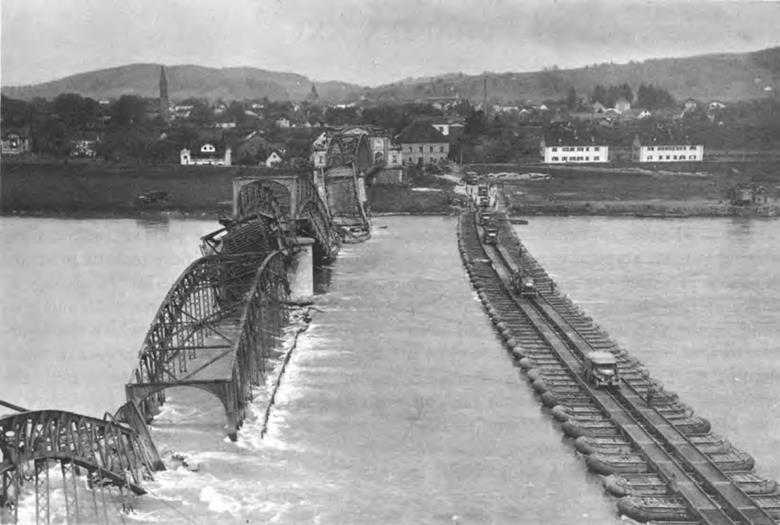
Steel treadway bridge from Simbach, Germany, to Braunau, Austria, replaces the one destroyed by retreating Germans, May 1945
and talent in order to win the race against time. But since such investigations could be made only by sacrificing production of items already in the field, they had to be of a most compelling nature. Perhaps a greater investment in the field of mine detection and clearance might have paid substantial dividends. Perhaps, too, the Engineer Board and OCE were slow to grasp the potentialities of the Bailey and treadway bridges and to discard other, less suitable, types. This hesitation in choosing between the tried and the untried was costly in terms of precious technical talent. Yet in the face of the accidents which occurred on the treadway, the board went ahead successfully to convert this bridge into a safe structure. This improvement in bridging, together with the development of the tank dozer, were outstanding achievements made under great pressure for time and other handicaps common to a war economy. Partly as a result of these accomplishments, but even more as a result of the firm foundation laid during the period before Pearl Harbor and the wise decision to concentrate upon production, the engineer soldier was well equipped to carry out his work.