Chapter 11: The Search for Increased Fire Power in Ground Warfare: Launchers and Fire Control
Fire power on the battlefield had a twofold mission: to destroy hostile troops and matériel, and to facilitate maneuver of friendly forces by compelling the enemy to deploy and seek shelter. To fulfill this mission effectively, fire power had to be capable of responding to the tactical requirements of combat troops from the rifleman to entire corps and armies. Although the theoretical ideal would have been a single weapon answering all those needs, no such solution was feasible up to the end of World War II, Physics, chemistry, and the other sciences involved in the design of weapons had not discovered the principles or materials to equip the individual with the fire power of heavy artillery. The ideal could only be approached through the development of weapons that narrowed the gap between the destructive effect of large-caliber guns and that of small arms. The extent to which that gap was narrowed between 1940 and 1945, and the successes and failures experienced along the way, make up the story of Ordnance research and development in the search for greater fire power in World War II.
The Scope of the Problem
Raising the fire power of American ground forces was a slow and difficult process. During the interwar years the Ordnance Department stood practically alone in exploring the data basic to the construction of improved firearms. Virtually no American in civilian life had concerned himself with investigations to resolve the numerous mysteries of ballistics, with the development of high yield-strength steels for more powerful guns, with the design of more accurate and safer fuzes, or with the composition of better military propellants and high explosives. That progress had been made in these fields, or that American know-how in the art of weapon design had survived the interwar period at all, redounds almost exclusively to the credit of the Ordnance arsenals and their laboratories.1
Efforts upon the outbreak of war in Europe to purchase indulgence for past sins of omission came too late. True, the sudden increase in appropriations
permitted the arsenals to reopen shops and augment skeleton staffs, but the years lost could not be brought back. The emergency was too pressing, the time lag between the beginning of research and development on new matériel and its readiness for issue to troops too great to permit the diversion of limited available talent and facilities to fundamental innovations. Aside from one or two exceptions, American combat troops consequently entered the war and won their victories with basically the same types of weapons as those of World War I: the rifle, machine gun, mortar, field gun, and howitzer.
Unlike the designer of military motor vehicles, who could draw on the vast experience and technological progress of private industry in supplanting the horse with the internal combustion engine, the designer of military small arms and artillery was, in a manner of speaking, limited to breeding a better horse. His wartime efforts focused primarily on bettering the performance of existing weapons and adapting them to novel tactical requirements. Amphibious, jungle, and airborne operations, improved protective characteristics of potential targets such as the high speed and thick armor of modern tanks, demanded not only lighter weight and greater mobility, but also greater hitting power, greater accuracy, and higher rates of fire than ever before.
Serious problems arose at every step toward those goals, and the solution of one difficulty immediately begot a host of others. Gun metallurgy, for example, made tremendous strides in developing better steels. Whereas prewar cannon steel had an elastic limit of roughly 60,000 pounds per square inch, some steels developed during the war had a limit of 160,000 pounds.2 But translating that progress into more powerful guns presupposed the development of more powerful propellants with decreased erosion, flash, and smoke characteristics. And the higher initial velocities of projectiles attainable with these propellants in turn posed complex problems in connection with rotating bands, clearance and crimping of cartridge cases, and twist and form of tube rifling. These were but some of the hurdles in interior ballistics, that part of the science dealing with the motion of projectiles concerned with their behavior while still in the gun. Equally complex problems, discussed later,3 presented themselves in exterior and terminal ballistics, realms of science dealing with the motion of the projectile after it leaves the muzzle and its behavior upon impact on the target.4
World War II marked the first time in history that American troops were equipped with a complete line of all required types of weapons, from side arms to the heaviest artillery piece. Not all these weapons were actually new developments; many of the best known, such as the 75-mm. and the 155-mm. guns, had been adapted from foreign designs. But unlike their fathers in World War I, US troops between 1941 and 1945 were never dependent on foreign matériel. Thanks largely to the farsightedness of the Westervelt Board of 1919, modern versions of all but three large-caliber weapons—the 120-mm. antiaircraft and 8-inch field guns and the 240-mm. howitzer, all completed
early in the war—stood ready by the time of Pearl Harbor.5
Until America’s enemies and theatres of operations were actually known, the required characteristics of weapons were of necessity determined largely by guess. Development after 7 December 1941 therefore became a hectic race against the clock to adapt rifles, guns, and howitzers to service in arctic cold, desert heat, and jungle moisture, and at the same time to keep their performance abreast of an enemy as technically competent as the Germans. The task was so great and so intricate that even its most significant aspects can merely be touched upon in these pages.
Increasing Muzzle Velocities
Perhaps the best-known and most urgent phase in the development of greater fire power was the quest for increased muzzle velocities. Muzzle velocity, the speed with which the projectile leaves the bore of a gun, was important primarily in direct-fire weapons such as field guns and tank and antitank guns, because it determined range, flatness of trajectory, and penetrating power of the projectile. In indirect- or plunging-fire weapons such as howitzers and mortars, on the other hand, it controlled largely range alone.
The muzzle velocity of a given gun could be stepped up in several ways. The tube might be lengthened, the projectile made lighter, the propellant charge increased, or more powerful powder employed. Each method had its drawbacks. Lengthening the tube, for example, meant unbalancing the piece and limiting its mobility, as was illustrated by the superlong cannon of the German Tiger II and Panther tanks which, for all their power, seriously handicapped the vehicles in crossing ditches or passing through towns and forests.6 Again, an increased or more powerful propellant charge built up greater gas pressure that might rupture the tube unless its walls were thickened or made of stronger steel.
While gun designers based many new weapons on existing ones or their components in order to permit quantity production in the shortest time possible, they obtained improved performance, as well as the weight savings required by mobile warfare, by use of new and better materials. The story of the 76-mm. tank gun was a case in point. As soon as events in North Africa indicated the need for a gun of greater power and penetrating ability than the 75-mm. gun M3 of the Sherman tank, Ordnance engineers began work on just such a weapon. If the new cannon were to reach the battlefield quickly and in quantity, it would have to fit into the tank without major modifications to turret or mounts and at the same time obviate need for the lengthy process of developing new ammunition. Taking the existing 3-inch armor-piercing round as their starting point, Ordnance engineers designed around it a new high-velocity weapon made of high-quality steel. The whole development process was incredibly short. The project was initiated on 20 August 1942 and the completed gun, designated the 76-mm, M1, was standardized on 10 September, less than a month later. That same autumn, eighty of the new guns were produced and ready for
installation.7 Compared with the 75-mm. gun M3, the 76-mm. gun M1 weighed roughly 300 pounds more, but attained a muzzle velocity approximately 600 feet per second higher firing armor-piercing ammunition and almost 1,300 feet per second higher firing high-explosive ammunition. Realizing that still heavier guns would be required to insure American superiority on the battlefield, General Barnes in September 1942 ordered the initiation of a project adapting the high-powered 90-mm. antiaircraft gun to use in combat vehicles. Design of the 90-mm. tank gun T7 was completed in December of the same year, but neither the 76-mm. nor the 90-mm. weapons were destined to see action until the autumn of 1944.8
Despite the urgent representation of Ordnance officers, all efforts to get the high-powered tank guns to the front failed. In the case of the 76-mm. gun, for example, the first production weapon mounted in a tank was successfully fired from a pilot tank in September 1942, but in November the Armored Force recommended that quantity production be deferred until it had thoroughly tested several pilot models and determined their tactical suitability. The Ordnance Department was specifically instructed to limit procurement to twelve Sherman tanks mounting the 76-mm, gun. Shortly thereafter the entire project was dropped and was not revived until the following spring when the Army Ground Forces approved the diversion of enough tanks mounting the new gun to equip one company. As a result of these and similar delays, the first production tanks equipped with the 76-mm. gun were not completed until January 1944. Almost identical circumstances kept the 90-mm. weapon off the battlefield. Until autumn of 1943 all attempts to interest the Army Ground Forces in the weapon were unsuccessful. As a result, the 90-mm. gun motor carriage M36, the first vehicle to mount the cannon, was not standardized until June 1944, and in July General Dwight D. Eisenhower had to send Brig. Gen. Joseph A. Holly, the chief of his Armored Fighting Vehicles and Weapons Section, to the United States to expedite getting the best American armor-piercing gun to the troops.9
The Army Ground Forces objected in particular to what they believed was a trend toward making guns bigger instead of better. In connection with an Ordnance proposal to mount a 105-mm. on a projected tank, for example, the AGF stated:
... in our army we are using an increase in mass of the projectile rather than velocity to secure improved penetrative ability. This condition is intolerable and must be corrected at the earliest possible date through the use of cannon specifically designed for use in tanks and gun motor carriages and by the use of new propellants which will furnish very high velocities with greatly reduced smoke and flash as compared to present propellants. The deficiencies in the penetrative power of our present 75-mm, 76-mm and 90-mm guns as compared to comparable German cannon is a matter of grave concern to our Ground Force commanders and this headquarters. ...10
So far as penetrative power was concerned,
the problem was far less one of muzzle velocity than one of production limitations. For when firing the most powerful ammunition, tungsten-carbide core, the most powerful German tank gun—the 8.8 cm. Kw. K. 43 (L/71) of the Tiger II or Royal Tiger—and the US 90-mm, gun M3—of the gun motor carriage M36 and the Pershing tank—had almost identical velocities: the German gun attained 3,240 and the American 3,350 feet per second. German no less than American ballisticians and designers were aware that increasing the muzzle velocity and penetrative power of a given weapon beyond a certain point created problems such as excessive erosion, as well as a need for longer tubes, chambers, and cartridge cases, but did not produce a greater effect beyond the projectile’s point of impact. The Germans, too, therefore chose the quicker and more reliable course of using a bigger gun when they wanted a greater destructive effect. German vehicle armament such as the 128-mm. cannon of the Jagdtiger or tank-destroyer version of the Tiger II, as well as the 150-mm. weapons under development for superheavy tanks such as the 180-ton Maus, which was almost completed by the end of the war, gave ample evidence of the definite tendency toward bigness.11
Perhaps the best illustration of the limited usefulness of hypervelocities and extraordinary penetrating power were the experiments with tapered bore weapons. In these, the projectile was squeezed to a smaller diameter as it traveled from the breech to the muzzle. Presenting a large cross-sectional area to the powder gases and a small cross-sectional area to the air, the projectile attained high velocity while encountering little air resistance. American experiments in the application of this principle indicated that cylindrical bore artillery employing special projectiles served every purpose of tapered bore guns and at the same time avoided intricate machining problems. The Germans, after diverting plant facilities for the actual production of three sizes of tapered bore antitank guns, eventually came to the same conclusion and dropped the project. Although light in weight and capable of good armor penetration, the guns were difficult to manufacture, had a limited effective range because of rapidly decreasing velocity, wore out after about 1,000 rounds, and caused little serious damage after the small projectile cores had penetrated the tank armor.12
Rocket Launchers
Another important phase in the Ordnance Department’s quest for greater fire power began when tactical developments abroad demonstrated the urgent need for hand and shoulder weapons of so radically improved performance as to exceed the limitations of conventional design. Even before the attack on Pearl Harbor, the fighting in Europe and North Africa showed that currently used small arms were incapable of defeating modern armor. American designers who meanwhile were developing small-size missiles that, by embodying the shaped-charge principle, would penetrate great thicknesses of steel plate, likewise failed when they tried to launch them. The recoil
induced in weapons based on the conventional principle of internal combustion severely damaged the launching device even when it rested on the ground; firing it from the shoulder was obviously out of the question. The search for a practicable means of getting a shaped-charge missile on its way to the target finally ended when recourse to rocket propulsion eliminated recoil altogether. The launching device, the bazooka, was merely a tube, open at both ends, that fired an electrically triggered rocket. While the new weapon had less accuracy and range than a rifle or machine gun, it lent the individual soldier hitting power heretofore possible only with artillery guns.
Although the most difficult problem in the development of the bazooka centered on its propulsion, several significant modifications to the launcher itself proved necessary during the course of the war. Thus, when reports from the field began pouring in late in 1942, a number of changes were introduced—a web sling to facilitate carrying, a shield to protect the face of the soldier firing the launcher, and a correction to ensure contact between the launcher and the band on the rocket. A trigger-operated magnet replaced the batteries powering the firing mechanism of the first models. The new device, relatively impervious to extremes of temperature and dampness, facilitated field maintenance and supply, particularly in the tropics where fungus tended to corrode and affect electrical connections. Wire-wrapping the launcher tube to give greater strength and eliminating the contactor box constituted modifications marked enough to require by July 1943 a new model designation, the M1A1.”13 More drastic changes followed almost at once when the Commanding General, Airborne Command, requested a model that could be taken apart and carried in two approximately equal loads for paratroop use. The using arms also asked for a better sight, addition of a safety switch, improved shape of a two-position stock, and other lesser modifications. These were incorporated in the rocket launcher standardized in October 1943 as the M9. In the last model standardized before the war ended, weight was reduced more than five pounds by making the tube of aluminum instead of steel. This, the M18, never got to the front.14
Despite the simplicity of the rocket launcher as compared to a rifle, machine gun, or conventional artillery piece, the bazooka’s development again illustrates the fact, familiar to every designer, that one desired change usually entails a host of other changes. The two-piece bazooka soon showed weakness in the coupling ring by which the two lengths of the launcher tube were screwed together; much sturdier forged coupling components then had to replace the original ring. Substitution of the mechanical electric firing mechanism for the batteries solved some problems only to create others when pronounced deviations in performance appeared in the field. To cope with this situation the Department had to procure testers enabling Ordnance units in the theatres quickly to determine whether or not the electric firing mechanisms were functioning. The testers in turn required modifications as faults showed up.15 The noteworthy feature of this story of constant redesign is that production of the bazooka continued uninterrupted,
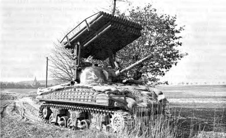
Multiple rocket launcher T34 mounted on a Sherman tank
and, imperfections notwithstanding, Allied troops in all parts of the world used it with great effectiveness.
Despite the wartime progress in rocket development, many unsolved problems remained. Neither shoulder weapons such as the bazooka nor multiple launchers such as the 4.5-inch T34, a sixty-tube cluster fired from the Sherman tank, were very accurate. Their primary value lay, in the first instance, in giving the foot soldier for the first time in history the equivalent of hand-carried artillery powerful enough to stop tanks, and in the second instance, in providing a ground weapon that could quickly cover an area with a hail of fire. Compared with conventional artillery, their only unquestioned advantage was the low cost of the simply made launching device. Otherwise, their inaccuracy made rocket weapons a poor substitute for artillery.16 That the enemy experienced similar difficulties is evidenced by the comment of a German general who, when asked his views on the Panzerschreck, the counterpart of the bazooka, replied: “Faute de mieux, on se couche avec sa femme.”17
Recoilless Rifles
The last year of World War II saw the introduction of two new weapons with many of the advantages but substantially fewer disadvantages than those of rockets: the 57-mm, and 75-mm. recoilless rifles. Both fired regular artillery-type shells at velocities and with an accuracy comparable with those of standard guns, but entirely without recoil. Both were light
enough to be hand-carried into action. The 75-mm. model could be fired from the standard tripod of the .30-caliber machine gun; the 57-mm. rifle weighed a mere 44 pounds and was readily fired from the shoulder or from a combination bipod-monopod.18
Development of the recoilless rifles took an amazingly short time. Early in 1943 the Small Arms Division of the Research and Development Service commenced a study of the principles involved, and shortly thereafter directed Frankford Arsenal Laboratory to make a detailed analysis. With help from data on foreign non-recoil guns, derived primarily from German specimens captured in North Africa, and a complete computation of interior ballistics, the whole basic theory of the projected weapons was worked out and the first pilot model completed on 27 July. Test results from the pilot formed the basis for designing the weapon proper, and in October the first gun was completed. Designated Rifle, Recoilless, 57-mm., T15E1, the weapon was successfully proof-fired at Aberdeen Proving Ground between 8 and 10 November. Design of the 75-mm. version began in March 1944 and the first pilot was completed and fired that September.19
The principle of the recoilless feature was relatively simple. A perforated cartridge case allowed a portion of the propellant gases to escape to the rear through vents in the breech. Pre-engraved rather than solid driving bands on the projectile obviated problems of engraving pressures and contributed to the smooth functioning of the rifle. Anyone doubting its performance could put a glassful of water on the tube and fire without spilling a drop.
Reports from users overseas were enthusiastic. Both in the Pacific and in the European theatres the 57-mm. and 75-mm, recoilless rifles proved highly effective against point targets such as tanks and pillboxes. Airborne troops, who at last had a really light-weight, high-powered weapon for their specialized missions, testified, “The effective range of the [75-mm. recoilless] gun for direct fire is the range of visibility. It is as accurate as an M1 rifle and you can hit a tank any place you desire. ...”20
Very Heavy Artillery: “Little David”
But while the mobility of modern armies gave rise to the development of powerful, close-support weapons such as the bazooka and the recoilless rifle, it well-nigh doomed to extinction those types of artillery that by their very size and weight were ill-adapted to overseas shipment as well as to high-speed, cross-country warfare. In the age of attack and heavy bombing aviation, airborne operations, and, finally, supersonic rockets and guided missiles, the siege howitzer and superrange gun were both too vulnerable and too limited in usefulness to warrant the man-hours and materials that went into making and operating them. Although the Germans devoted untold efforts to the design and construction of large-caliber railway mounts and oversized mortars, these monsters made little else than good news copy. The 80-cm. “Gustav,” for example, a railway gun firing a 16,540-pound projectile over a range of over 29 miles (51,400 yards), required a complement of some 40 separate cars,
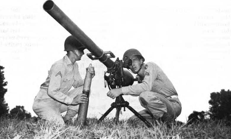
75-mm. recoilless rifle M20
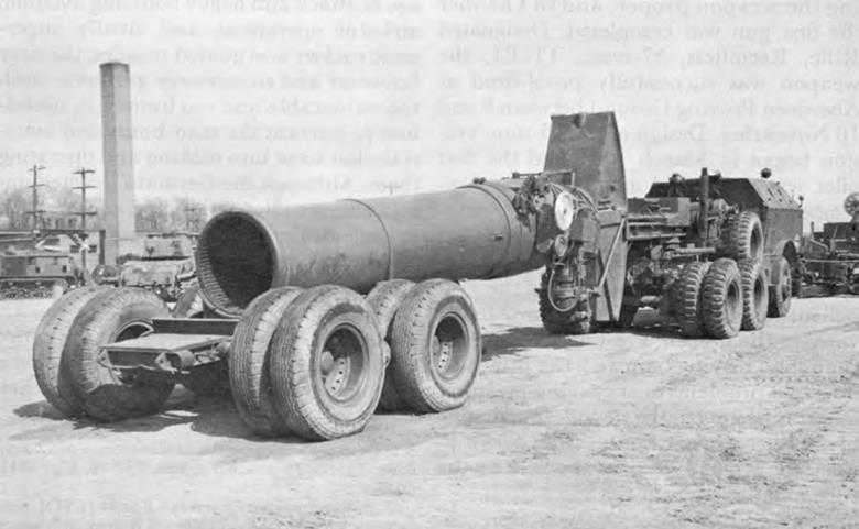
“Little David” 914-mm. mortar T1
could move only on double-track lines, and took 45 minutes just for the loading of a single round. Its performance at Sevastopol and Leningrad was disappointing.21
The Ordnance Department developed only one superheavy weapon, the 914-mm. mortar T1, “Little David.” For sheer size, it topped anything even the Germans had ever attempted. Comprising two major assemblies, the tube and base, it weighed 172,900 pounds. Despite the necessity of using two powerful tractors to tow tube and base, officers of Research and Development Service quaintly pronounced this giant “highly mobile.” Its projectile weighed 3,650 pounds, including 1,589 pounds of high explosive, and was fired by a maximum propelling charge of 218 pounds of powder. Its range was roughly 9,000 yards. Five men were needed to load the propelling charge, two to ram the projectile into the muzzle, and two equipped with hand brushes had to crawl into the bore to clean it.
Development on Little David began in March 1944 as the result of a requirement for a new weapon to destroy partially buried, reinforced-concrete works that the Army expected to meet in the ETO. By 31 October the tube and base section of the first pilot had arrived at Aberdeen. Subsequent test firings revealed the need for several modifications in the base components and the method of emplacement because of the severe shock of firing and the heavy recoil. Following numerous test firings and further changes of tube, base, and ammunition, the weapon was demonstrated to General Marshall, General Somervell, and other high-ranking officers on 16 July 1945. The end of hostilities soon after canceled plans for shipping the weapon to the Pacific and prevented the use of Little David in combat.22
Fire Control
Since the most efficient performance of a weapon in firing its projectiles is useless if fire is so faultily directed as to miss the target, one of the most important Ordnance efforts to provide Allied forces with greater fire power was to obtain more accurate fire control. Devices for observing targets and aiming weapons had been under study and development by Ordnance engineers for many decades before 1941, but World War II brought a need for a wide variety of new and improved fire control instruments both for antiaircraft batteries and for firing at fast-moving ground targets such as tanks and trucks.23 The basic principles of fire control instruments used in World War II were the same as those of World War I, but after 1940 Ordnance engineers worked steadily toward increasing the accuracy and range of fire control matériel, reducing the work required of gun crews, providing illumination for night firing, and designing instruments that would be light enough for easy transport and yet strong enough to withstand rough handling. In addition, Ordnance engineers were constantly faced with the necessity of designing instruments that, although built with the precision of a fine watch, could be speedily mass produced with minimum use of skilled manpower and strategic materials.24
The term “fire control instruments”
covers a large number of items, ranging from the simple iron sights on a .30-caliber rifle to the complicated instruments employed in directing a large artillery piece at an unseen target many miles away. It includes both “on-carriage” and “off-carriage” equipment, the former consisting chiefly of such instruments as sighting telescopes and elevation quadrants, and the latter including range finders, binoculars, observation telescopes, compasses, and plotting boards. A mere listing of all the fire control instruments used in World War II, with model numbers and modifications, would fill a small book. Discussion here can cover only the general principles guiding the research and development work on a few representative classes.25
Telescopes and Binoculars
At the start of World War II Ordnance designers of telescopes and binoculars were seriously handicapped by a lack of domestic production of many types of optical glass. Before 1941 the United States had imported from Germany types not made in America, but the outbreak of war abruptly cut off this source of supply. As a result, Ordnance designers did not have a free hand in developing instruments embodying the most advanced scientific principles since they could use only the types of optical glass that the United States glass industry could produce in quantity. In 1940 only five standard types could be used, and not until 1944 was a wide range of glasses available.26 Not only the Ordnance Department but also the Navy, the Army Air Forces, and other branches of the service were keenly interested in sighting, aiming, and photographic equipment. In many instances the development and production problems of all services were closely related. As none of the military agencies had adequate facilities and sufficient trained personnel to carry on single-handed the research required for an aggressive development program, they all turned for assistance to leading manufacturers of optical instruments and to university laboratories. In this process the National Defense Research Committee and other government agencies performed invaluable service in coordinating and directing a large share of the essential research.27
The fact that each caliber of gun posed special problems for the designers of fire control matériel was another major influence on Ordnance research and development in this field. No matter what efforts were made at standardization, sighting and aiming equipment, particularly telescope reticles, had to be tailored to fit the individual weapon and its ammunition. Not only did each caliber require a special telescope, but each telescope required a special mount, and in many cases Ordnance engineers devoted as much effort to the design of the mount as to the design of the telescope itself. The mount had to hold the telescope in exactly the right position in relation to the gun tube and the control gears, and had to provide for carefully
regulated movement of the telescope over a wide range of vision. Since nearly every new design or major modification in weapons and ammunition demanded some change in the sighting and aiming apparatus, the development of fire control instruments and mounts was a never-ending process.
In designing telescopes to meet the requirements of the using arms, Ordnance engineers frequently found themselves faced with the task of reconciling the irreconcilable. Three of the fundamental characteristics of a telescope—degree of magnification, extent of the field of view, and size or complexity of the instrument were so interrelated that a gain in one characteristic usually meant a loss in one or both of the others. Greater magnification could be achieved only at the cost of decreasing the field of view unless additional elements were used and the telescope was made bulkier and heavier. Similarly, the field of view could not be widened without sacrificing magnification or enlarging the instrument. Because it was impossible to design a telescope that was at one and the same time small in size, powerful in magnification, and broad in its field of view, Ordnance designers had to evaluate the importance of each of these characteristics in terms of the purpose for which each telescope was intended and then adopt the most acceptable compromise.
As weapons with greater recoil, such as the 3-inch gun, came into more general use, need arose for telescopes with a longer “eye distance,” the distance between the observer’s eye and the eyepiece of the telescope. This introduced another set of irreconcilable factors. When, for example, the Tank Destroyer Board requested a 3-power direct-sighting telescope with an eye distance of eight inches for use with the 3-inch gun motor carriage, the Ordnance Department had to report that telescopes built to these specifications would result in such a restricted field of view, such a small exit pupil, or such a large instrument that none would be acceptable. A close approximation to the desires of the Tank Destroyer Board was achieved in the spring of 1943 with the T108, a 3-power telescope with an eye distance of 6.5 inches. A novel feature of this instrument was its use of plastic rather than glass optics. Although the Tank Destroyer Board received the T108 enthusiastically, the Ordnance Department recommended that it be given only limited procurement status until further experience with plastic optics under field conditions had been gained. When produced with glass optics, this telescope was standardized in the spring of 1944-as the M79C.28
The straight tube telescope was one of the most extensively used instruments for the control of direct fire, but it had certain disadvantages, chief of which was that the gunner in sighting had to stand behind the gun where he might be in the way of other members of the gun crew. This drawback was eliminated by the use of a more complicated instrument, the elbow telescope, which permitted the gunner to stand to one side of the gun. With the exception of its roof prism, which bent the light rays at a right angle, the optical characteristics of the elbow telescope resembled those of the straight telescope and followed the same course of development. Roof prisms, however, were difficult to manufacture in
quantity, and during 1942 production lagged behind military requirements. To meet this exigency Frankford Arsenal in the fall of 1942 constructed an experimental telescope with an inverting prism but, by the time it had been tested and found satisfactory by the using arms, production on the roof prism instruments had caught up with demand. The remarkable increase in the roof prism production rate resulted from the cooperative efforts of the NDRC, the Bureau of Standards, and the Ordnance Department in developing a method for using grinding machines to perform a large part of the work formerly done by hand by skilled craftsmen.29
The panoramic telescope was far more complicated than either the straight tube or elbow telescope, and to improvement of its design Ordnance engineers devoted a large share of their efforts. The panoramic telescope combined a telescope and periscope so that the observer, without exposing himself or changing his position, could see in any direction. It could be used to lay the weapon in direction for indirect fire or to sight for direct fire. At the start of World War II the standard panoramic telescope was the M12, adopted in August 1940 to replace the M1917, which had been in general use since World War I.30 It incorporated improvements in optical design and manufacturing methods that had been made during the interwar years. The M12 originally had a reticle similar to that of the M1917, with horizontal and vertical crosslines and a mil scale on the horizontal line but, as this was not suitable for direct fire against moving targets, it was replaced on medium artillery weapons by a grid-type reticle with vertical lines to measure lead and horizontal lines to measure range. This reticle enabled one man to aim the gun quickly at a moving target, but as a rule the panoramic telescope was used only for laying the gun in direction while a quadrant was used for laying it in elevation for indirect fire against a distant, stationary target.31
In 1940, when the task of supplying the expanding Army with thousands of binoculars suddenly loomed large, the standard military binocular was the Type EE, a World War I instrument. The inadequacies of the “Double E” binocular had been recognized as early as 1921 when responsibility for development of binoculars had been transferred from the Signal Corps to Ordnance, but no substantial progress had been made during the peace years toward designing a new binocular or modifying Double E to make it waterproof and shock resistant.32 To meet the urgent supply requirements established in 1940, the Ordnance Department was forced to supplement existing stocks of Type EE by purchasing binoculars of commercial design that could be speedily produced by the optical industry. To avoid the delay involved in developing, testing, and setting up production facilities for a new design, a Bausch and Lomb binocular with approximately the same military characteristics as the Type EE was standardized in November 1940 as the M3, and others of the same type manufactured by other companies were later standardized under different model numbers.33 After
thousands of M3-type binoculars had been issued, reports came in from overseas observers describing the disastrous effect on these instruments of unavoidable rough handling, submersion in water during landing operations, and exposure to extremes of temperature. The M3 was then redesigned to make it stronger and more nearly waterproof, and, at the same time, the laboratory at Frankford Arsenal developed a new compound, capable of withstanding extremely high and low temperatures, for sealing the optical lenses to the metal cells. To prevent the condensation of moisture on the optical elements within the binoculars, a small amount of silica gel was placed in each to absorb whatever moisture penetrated the casing. The new model was standardized early in 1943 as the M13 and continued, with only minor modifications, as the standard military binocular for the rest of the war.34
Another widely used instrument for spotting targets and observing the effects of artillery fire was the battery commander’s telescope, commonly called the BC scope. During World War I, and for many years thereafter, the standard BC scope was the M1915, a 10-power binocular with a very narrow field of view. Various attempts were made to widen the field, provide illumination for the reticle, and make other modifications in this instrument during the 1920s and 1930s, but it was not until 1935 that the Field Artillery Board, after summarizing the deficiencies of the M1915, called for the development of an entirely new instrument. The field of view of the M1915, the board pointed out, was so small that, when observation of fire was made, many rounds fell outside its field. In addition, its light-transmitting power was low and its angle-measuring system inaccurate and hard to keep in adjustment.35
Nearly seven years elapsed before a newly designed BC scope was ready for test early in 1942. The new instrument had a larger field of view, better light-transmitting qualities, an improved reticle, and other advantages. Although the Field Artillery Board found it superior in many respects to the M1915, it also found the new instrument inaccurate in the measurement of angles, largely because, by specification, it was designed for use by an observer wearing a gas mask. When the Field Artillery Board dropped this requirement, the telescope was modified to correct its inaccuracies and was standardized as the M65 early in 1943. While this work was in progress, the M1917, a telescope of French manufacture similar to the M1915 but of higher power, was provided with an instrument light and adopted as substitute standard.36
Range Finders
In the development of range finders for use with field artillery and heavy infantry weapons, Ordnance engineers faced many of the same problems encountered with telescopes and binoculars. Since range finders operate on the principle of measuring the acute angle of a right-angled
triangle that has the range finder as its base and the target as its apex, the accuracy and effective range of the instrument depend in large measure on the length of the range finder and its degree of magnification. A range finder with a tube 30 inches long obviously has more limited potentialities than does one 30 feet long. Large range finders could be installed at fixed installations such as seacoast artillery batteries, but, for an army on the move, the range finder had to be small, usually not more than one meter in length, and easily transported. The smaller range finders, moreover, had to be rugged enough to maintain their precise optical arrangements intact under rough handling.37
The standard Field Artillery range finder of World War I was the one-meter M1916, an inverted-image, coincidence-type instrument that measured ranges from 400 yards to 20,000 yards. With slight modifications this instrument remained standard for the next twenty years, although Ordnance and the Field Artillery both saw the need for a range finder that would be lighter, more rugged, less visible, and better adapted for quantity production. Late in 1939 work on three improved experimental models was begun, but none proved markedly superior to the M1916. Finally, in the summer of 1942 samples of one-meter range finders being produced in Canada for the British Army were procured for test by the fire control laboratory at Frankford Arsenal and by the Field Artillery Board and the Infantry Board. One of these British instruments, designated T16, was lighter, less bulky, and more accurate than any other range finder yet tested. Furthermore, it was more easily manufactured, cost less, and used less strategic material. It was therefore standardized in December 1942 as the M7 for field artillery use and, with modifications, as the M9 for infantry. At the same time the M1916 was classified as limited standard and development of all other experimental one-meter range finders was canceled.38
Sights for New, Types of Weapons
The introduction during World War II of the recoilless rifle and the bazooka brought the need for new sights but posed no serious fire control problems. The absence of recoil with the 57-mm. and 75-mm. recoilless rifles actually simplified sighting, as it permitted the use of telescopes with short eye distances.39 When the earliest bazookas appeared in 1942 they were equipped with simple ring sights, which did not prove accurate enough to satisfy the using arms. An optical sighting device was then developed but had to be abandoned because the calcite crystals required for its manufacture were not available. The hinged-bar sight, adopted instead, showed appreciable inaccuracy in alignment when in combat and was soon replaced by a reflecting sight that could be mounted without modification of either launcher or sight bracket. It consisted of a plane disc-shaped ocular having a small reticle at its center opposed to a concave transparent mirror that partially reflected the reticle pattern and partially transmitted light. All bazookas produced in late 1944 and in 1945 were equipped with these reflecting sights.40
Night Lighting Devices, Filters, and Lens Coatings
The development of special night lighting devices for fire control instruments was a minor but significant field of research during World War II. During World War I ordinary commercial flashlights shielded with a helmet or other object had been used for illuminating the scales and levels of aiming devices, but during the 1930s Ordnance engineers turned their attention to the development of lights specially designed for fire control instruments. The battery commander’s telescope M1915 was the first for which a lighting unit was standardized.41 Designated Instrument Light Ml, it consisted of a battery case with one dry cell clamped to the telescope and a flexible cord leading to a lamp that could be directed on the scale and level. For large-caliber weapons elaborate lighting systems powered by storage batteries were developed only to be rejected by the using arms on the ground that they were too difficult to install and service, used an excessive amount of exposed cable, and were too expensive. As a result, the flashlight type using standard dry cells was adopted for all fire control instruments.
A different approach to the night light problem was through the use of materials that glowed in the dark. As early as 1939 the Field Artillery Board had tested reticles with luminous lines and dots but had rejected them because they glowed only after it was too dark to see the target.42 Luminous materials were successfully used on the level vials of the gunner’s quadrant, an instrument that had long been an especially difficult problem because it was normally used in an exposed position and could not be illuminated by a conventional light without danger of being seen by the enemy. Early in 1944 luminous vials were tested by the using arms and approved for issue, with first priority going to units equipped with the 155-mm. gun and the 8-inch howitzer. Meanwhile, immediately after Pearl Harbor, General Barnes had hopes that infra-red illumination could be used for directing night fire, and a request went to NDRC to work out an electron telescope capable of penetrating darkness as well as fog and smoke. Even for small arms some efforts went into devising sights for night firing. While investigations of various methods proceeded in the United States, the problem was also explored in the United Kingdom. The Weapons Branch of the Ordnance Maintenance Division in the ETO reported late in 1943 that an illuminated collimator, attachable to rifle or carbine but easily removable for day service, had given satisfactory performance in tests at ranges up to fifty yards. But decision of the using arms that these devices were not needed canceled further work.43
Another minor but important phase of fire control research was concerned with antiglare filters and protective lens coatings. In October 1942 the Desert Warfare Board conducted tests on red, amber, and neutral filters submitted by the Ordnance Department, but reported that, although each had advantages under certain conditions, none was sufficiently helpful to warrant adoption. More successful were experiments with nonreflecting coatings on glass surfaces and the use of solid glass prisms in periscopes in place of mirrors. All
during the war years Ordnance engineers carried on numerous experiments to develop antirain and antifog coatings, hoods for protection against sun and rain, and mechanical modifications to increase ease of operation. An Ordnance detachment tested the performance of all types of fire control equipment under conditions of extreme cold at Fort Churchill in Canada during the winter of 1943–44 and brought back much valuable information on both design and maintenance. In June 1944 Frankford Arsenal formed a committee to study the protection of fire control instruments and their carrying cases from the ravages of fungus growth and other types of deterioration experienced in tropical climates. The committee directed its efforts chiefly toward the use of protective coatings, the development of moistureproof sealing, the incorporation of silica gel desiccants, and the employment of a volatile fungicide within the instruments.44
Sighting Equipment for Armored Vehicles
The important role assumed by tanks and other armored vehicles in the late 1930s created new problems for the designers of fire control matériel, for it meant that guns used against tanks had to be aimed far more rapidly than in the days when they were employed only against stationary targets, and the tanks themselves had to be equipped with ingenious devices for observing and sighting. Broadly speaking, Ordnance designers met the first of these problems by developing telescopes with so-called antitank reticles, which enabled the gunner to take the proper lead on the target and adjust for range at the same time. A telescopic sight with an antitank reticle was standardized in 1938, as the M6, for the 37-mm, gun, then considered an antitank weapon, and other sights of similar design were developed later for other guns. To enable antiaircraft weapons to perform their secondary mission of firing at ground targets, they also were equipped with sighting telescopes having antitank reticles.45
Before 1940 the only way tank crews could make observations without opening the turrets and exposing themselves to enemy fire was through direct vision slots in the turret. These narrow openings were not satisfactory because they weakened the armor and exposed the crew to danger from shell fragments. In search of a better means of observation, the Ordnance Department in 1937 tested various devices operating on the periscopic principle, including the Gundlach periscope developed by an officer of the Polish Army.46 Foreign observers considered the Gundlach periscope superior to anything else available at that time, but it proved unsuitable for American tanks, which did not have enough space in the turret to permit the observer to move his head from side to side as the periscope required. In the fall of 1940, therefore, Ordnance engineers began work on the design and manufacture of two experimental tank periscopes, the Ti and T2, each containing a straight telescope for gun sighting. As these periscopes were linked with the gun so that their line
of sight moved with it, the gunner, without moving his head, could aim the weapon for direct fire simply by centering the proper telescope reticle markings on the target. The linkage mechanism was hard to keep in adjustment, but after completion of tests at Aberdeen Proving Ground early in 1941 the two periscopes were standardized as the M1 for the 75-mm. gun and the M2 for the 37-mm, gun. When the heavy tank M6 was standardized later, the M1 periscope, with a different telescope, was used with the heavy tank’s 3-inch gun.47 In spite of these developments, reports from overseas observers stated that, because of poor periscopic vision, tank crews generally preferred to fight with turrets open.48
Following standardization of the M1 and M2, several other periscopes were tested and adopted but it was not until 1943 that a major new development appeared. This was a periscope with one high-powered telescope on the right side for sighting distant targets and a periscope with a reflex reticle on the left side for sighting near-by targets. Frankford Arsenal in February 1942 submitted sketches of such a periscope with the designation T8, and completed two pilots by July. The T8 offered much greater accuracy and stability of bore sighting than did existing periscopes, but its manufacture required the use of highly skilled optical and mechanical workers for long periods of time, and the cost of each periscope amounted to approximately $1,000. After extensive tests the Armored Force Board and the Army Ground Forces concluded that one T8 was so much superior to existing periscopes that its standardization was warranted in spite of the high cost. After modifications to facilitate quantity production, the instrument was standardized as the M10 and was put into production in the summer of 1944.49
In addition to the periscopic telescope, tank gunners used a straight telescope mounted inside the tank for direct sighting through an aperture in the turret. To minimize danger to the crew, this aperture was kept as small as possible—no larger, in the early part of the war, than a .30-caliber bullet. The problem was to provide a telescope small enough to fit this keyhole-sized aperture, powerful enough to give adequate magnification and a wide field of view, and yet short enough to be used in the space available inside the turret. Progress toward meeting these specifications was steady, beginning in the fall of 1942 with standardization of the M51, a 3-power telescope with a field of view of more than 12 degrees. During the winter of 1942–43 several new telescopes with better optical characteristics were developed, and in July 1943 one was standardized as the M70. It was later replaced by a 5-power telescope, the M71, which had a wider field of view and increased light-gathering power. The M71 was standard equipment on nearly all tanks early in 1945. A major innovation in tank telescopes appeared near the end of the war when the M83, a variable-power instrument, was standardized. This telescope could be readily adjusted to provide 4-power magnification with a relatively wide field of view or 8-power magnification with a much narrower field. The former adjustment was used for aiming at
near-by targets or for locating distant targets and the latter for sighting on distant targets.50
Gyrostabilizers
In contrast to their success in improving telescopes and periscopes, Ordnance engineers made little progress in other areas. .In spite of persistent efforts to adapt infantry and field artillery range finders to tank use, no satisfactory range finder for tanks was developed. In 1944 and 1945 attempts were made to evolve an integrated tank fire control system that would properly relate the ranging, computing, and aiming functions, but at the end of the war this project was still in the development stage.51
More difficult than the design of sighting devices themselves were some of the problems of utilizing them to best advantage. To realize fully the benefits from a high-power tank telescope, for example, it had to be able to function while the vehicle was moving. If the gunner could accurately lay his weapon only at a dead stop, his tank might present, at least momentarily, a choice target for hostile artillery. Some means had therefore to be devised for stabilizing vehicle armament during travel over rough terrain. Borrowing a page from the Navy, which had long employed such a mechanism on its waterborne artillery, the Ordnance Department adopted the gyrostabilizer.52
The working principle of the gyrostabilizer rested on the well-known behavior of the gyroscope—a rapidly spinning wheel or disc that tends to resist movement away from the axis about which it is spinning. The gyro control, the heart of the gyrostabilizer, consisted basically of a gyroscope mounted on the gun cradle with its axis parallel to that of the gun. Any slight displacement of the gyro control from its vertical position set forces in motion that returned it, and with it the gun tube, to its point of origin. The gun thus maintained its aimed position while the tank moved over the rises and depressions of average rough terrain. But it is well to remember that the gyrostabilizer neither aimed the gun to begin with, nor kept it on target when the tank went up or down hill or when the target moved. Its sole function was to keep the manually aimed gun on a line of sight selected by the gunner.
The problems attendant upon the development of a gyrostabilizer for vehicle armament were numerous. Unlike the gyrostabilizer of the naval vessels, the entire mechanism had to fit virtually into a nutshell and had to withstand shocks far more severe than those occasioned by the buffeting of wind and waves. Despite the fact that at the outbreak of war development had barely passed the laboratory stage and the few stabilizers that did reach the front quickly went out of adjustment, subsequent improvements were marked enough to merit careful attention. When a newly designed mono-gyro control was found to increase the percentage of hits by a factor of two or three to one as compared
with unstabilized guns, the device was immediately placed in production. With further improvements, it was used thereafter on numerous light tanks, many of the medium General Grants, and the entire series of General Shermans.
Although their stabilized guns gave American tankers a clear-cut advantage over their opponents—most notably the Germans, who by the end of the war had not succeeded in building a workable stabilizer53—reports from overseas indicated limited use of the gyrostabilizer in combat. In 1943 an officer returned from the fighting in Sicily stated that despite very careful maintenance no one used the gyrostabilizer to good advantage. He believed that it had possibilities only if it were simplified and if extensive training were given the troops on its operation. All told, he thought gyrostabilizers not worth the effort to put them in tanks; accuracy of fire was so important that tank crews preferred to halt before firing.54 Again, a report on the ETO in late 1944 stated, “experience has proven that tank crews have no faith in gyrostabilizers and will not use them. No amount of training seems to convince the tank crews of the value of firing while moving. The gyrostabilizer is an expensive piece of tank equipment never used, and it could be left out of tanks scheduled for theaters of operations.”55 Consistent evidence in the same tenor finally moved Ordnance to recommend the abandonment of stabilizers, a step that would have permitted a reduction of both maintenance time and expense. But that recommendation was disapproved, and the stabilizer remained. Intensive training of troops in its use made its mark at the very end of the war. In mid-August 1945 AGF reported, “many tank battalions are using gyrostabilizers extensively,”56
Fire Control, or Seacoast Defense Batteries
Although none of the seacoast gun batteries guarding the coasts of the United States went into action against an invading enemy fleet during the war, for years before Pearl Harbor, and months after, the Coast Artillery Corps and the Ordnance Department devoted much attention to the development of fire control systems for these weapons. Since coastal guns, along with antiaircraft guns, were designed for defense of United States territory, they had high priority during the period when national military policy emphasized defense against invasion, and remarkable improvements were made in the speed, range, and accuracy of the guns to keep them abreast of developments in the design of naval vessels. The problems of designing fire control apparatus for seacoast artillery, though simpler in most respects than for antiaircraft, were nonetheless challenging. Seacoast guns had to be aimed rapidly and at long range against fast-moving, heavily armored targets in a field of fire that usually offered no landmarks or reference points. Because large seacoast guns wore out after firing only a few hundred rounds and could not be used again until they
were relined at an arsenal, it was highly desirable that the number of misses be kept to a minimum. Most of the instruments used for aiming seacoast guns were basically the same as those used with field artillery weapons, but others, such as gun data computers and transmission systems, were developed to meet problems peculiar to seacoast artillery.
During World War I many different instruments were needed to provide seacoast guns with accurate firing data. A typical position-finding problem required the use of a plotting board, set-forward rule, prediction scale, deflection board, range correction board, percentage corrector, and spotting board. As each of these instruments was operated by from one to four men, the number of “read and set” operations required, the time consumed, and the possibilities for error were all great. The Coast Artillery Corps as early as 1919 drew up specifications for a computing device that would perform many of these calculations automatically, thus saving time and manpower and eliminating some chances for error. Two decades of research and development finally led to the standardization in September 1940 of the gun data computer M1 for use with long-range batteries. It was a 5,000-pound instrument, approximately seven feet long, three feet wide, and three feet high, costing about $100,000. It consisted of nine interconnected units, a target position generator, wind component indicator, ballistic correction unit, predictor, range elevation converter, parallax unit, and three triangle-solvers. For use with small coastal guns, the Coast Artillery Board in the spring of 1941 recommended that a seacoast computer be constructed along the same lines as the electrical antiaircraft directors then under development. This recommendation led to the standardization in May 1943 of gun data computer M8.57
While work on gun data computers was under way, fire control engineers also investigated possible ways of transmitting data from observation posts to plotting rooms, and from plotting rooms to gun positions. At the start of the war data of this type were transmitted orally by telephone. The observers at each post took readings simultaneously at the sound of a bell that rang at stated intervals, and then telephoned the data to the plotters. This method of transmission was slow and offered many opportunities for error on the part of the operators; when gun data computers were adopted the oral transmission of data by telephone became definitely outmoded. To enable the computing devices to operate with full effectiveness, it was necessary to provide them with a constant flow of data transmitted instantaneously and accurately from the observing stations and a corresponding outflow of computed data to the gun positions. The latter type of transmission covered relatively short distances and posed less difficult problems than did the longer-range transmission of data from so-called base-end stations, which might be as far as thirty miles from the plotting room. Under the aegis of NDRC the various components of a long-range data transmission system were developed during 1942, including azimuth transmitters, elevation
transmitters, and corresponding receiving devices. Early in 1943 these items were standardized as parts of the computers with which they were used.58
The seacoast fire control apparatus used during World War II depended upon so many observation posts and such an elaborate system of communication, and operation presented so many technical difficulties, that competent authorities feared the system would collapse in an actual attack. Little use had been made of radar for directing fire of seacoast artillery, but its successful employment by the Army Air Forces and the Navy led, at the end of the war, to a study of its potentialities for seacoast defense. Yet two years after a decision of 1946 to install radar at all modern batteries, the plan was abandoned because of the increasing effectiveness of other means of defense.59 In 1948 all large-caliber seacoast guns and their fire control instruments were declared obsolete. Thus ended the long and important history of Ordnance efforts to develop instruments for aiming the large guns guarding the nation’s coastal frontiers.