Chapter 2: The Revolution in Equipment
The vigor displayed by the Engineers in arguing their case before higher echelons was equally evident in exhortations toward members of the Corps itself. The Engineer mission had not diminished but had gained in importance. Engineer techniques must match the tempo of the new tactics, ran the message of an Information Bulletin issued in July 1940. Engineer work must be carried out “at top speed.”1 The way troops were organized and the thoroughness with which they were trained would go a long way in support of this objective. But as basic to the creation of a new Corps of Engineers as to the creation of a new Army was the adoption of modern equipment. Since the Engineers were most concerned about their adjustment to the new tactics of infantry, armor, and air they were particularly interested in improving means for hasty road repair, emergency bridging, and construction of airfields. But no phase of engineer activity—whether in front lines or in rear areas—was left untouched by the revolution in equipment which occurred during the experimental years before Pearl Harbor.
The Process of Selection
Most of the steps in the selection of new equipment were carried out by the Engineer Board at Fort Belvoir, yet all sections of the Military Division were involved in the process to some extent. The Operations and Training Section determined the military need for each item. The Intelligence Section advised the board on mapping equipment. The Supply Section gave its views on sources of production. The group which worked most closely with the Engineer Board, the Development Branch, Supply Section, considered whether or not a particular line of development was feasible, offered technical guidance to the board’s staff, and passed upon the recommendations made.
Other helpful sources existed outside the Military Division. Much was learned from industry and the professions serving industry because most engineer equipment was either a standard commercial product or a modification of something already on the market. Other arms and services, particularly the Engineer officers serving with them, contributed concrete suggestions as well as complaints which spurred the Engineer Board to attempt improvements. The advice of the Navy and Marine Corps was sought in connection with camouflage, landing boats, and water purification. The Bureau of Standards conducted tests from time to time. After the organization of the National Defense Research Committee in June 1940, the Engineers utilized its facilities. Persons with something to sell, inventors, and just plain citizens offered their bit. Nevertheless, most suggestions about new
equipment originated in the Military Division in Washington or with the Engineer Board at Fort Belvoir. These agencies sought out new ideas in domestic and foreign technical magazines, sent representatives to meetings of technical societies, and scanned numerous patents. Particularly after the German advance into France, intelligence reports and general news items were studied intensively. As the ties with Britain were strengthened, Engineer officers were sent abroad to exchange information.
Memoranda, letters, and reports about new work to be undertaken and work already under way at the Engineer Board came to the “IN” box of Maj. Claude H. Chorpening, the chief of the Development Branch. Five and a half years at Fort Peck Dam, Montana, had taught him much about construction machinery. Chorpening gradually filled out his staff so that by summer 1941 it consisted of fourteen civil, electrical, and mechanical engineers, five of whom he had worked with at Fort Peck.
The close link between the Engineer Board and the Military Division was one way of assuring unity in doctrine, training, and equipment. Another was provided by drawing together the Engineer Board and the Engineer School. The Engineer Board in the formal sense consisted of a group of seven officers. By custom its president was the commandant of the Engineer School and at least two of its members were on that faculty. Two others might be on duty at OCE or at the school. Only two members, its executive officer and his assistant, were on the board’s operating staff. The formal board of seven officers came together for two purposes—to witness demonstrations and tests of equipment, and to pass upon recommendations.
Although the president of the Engineer Board exercised general supervision in matters of policy, it was the executive officer who was the active head and general manager.
From 1936 until his death in October 1939, the executive officer was Capt. James M. Young, who came to Fort Belvoir after supervising a number of New Deal construction projects in the west. Captain Young’s successor, Capt. William C. Baker, Jr., had been assistant executive officer since July 1938.
During Young’s tenure at the board funds were meager, part of its physical plant was run down, and its staff was small. During the fiscal year 1939, for example, Young had less than $ 100,000 at his disposal. Much of it went into patching up the World War I barracks, where offices and drafting rooms were located, and the two sheds and two warehouses, which also dated from 1918. By contrast, the shop and laboratory building, finished in 1935, took little from the budget. It was modern and sufficiently spacious for the experimental work of the six officers and forty civilians at the board in 1939. With so few employees, specialization was out of the question. As a consequence, the board’s organization was loose and the work performed by most personnel ranged over several subjects. In addition to his administrative duties Young carried a heavy load, working on bridging, construction machinery, and demolitions.
Money to add more officers, hire more civilians, and provide more suitable facilities was forthcoming after the fall of 1939. The funds available in 1939–40 jumped to over $300,000, the year following to over $2,000,000. By June 1940, Baker was directing a staff of 5 officers and 100 civilians. By June 1941 there were 453 civilian employees and 38 officers on full-time duty,
including one each from Field Artillery, Ordnance, and Air Corps.
The increase in funds for salaries and equipment gradually created an opportunity to specialize and to carry out a thorough program of study and tests. By 1 July 1941, the jobs assigned the board had been broken down and employees given specific duties in the many administrative units created. At this time 35 percent of the personnel were in the Engineering Division where the development program was concentrated, 44 percent in the Operations Division whose main job was the manufacture of searchlight mirrors, and 21 percent in the Administrative Division.
As personnel was hired and the board overflowed into another old barracks and a portable building, Kingman and Chorpening sought means of providing a modern plant. With $2,800,000 allotted from the President’s Emergency Fund they contracted for the construction of twenty-four permanent buildings, including three for offices, two for general storage, a central heating plant, and numerous special shops and laboratories. Begun in July 1941, none of the buildings was finished until after Pearl Harbor. Lack of suitable facilities plagued the board’s personnel before and throughout the defense period.2
Despite shortages of personnel and lack of facilities much was accomplished, particularly in the year and a half before Pearl Harbor. In the period May 1930–May 1940 only 34 single items and sets were added to the organizational equipment of engineer troop units. Between May 1940 and October 1941 the total number of single pieces of equipment rose from 22 to 139 and the number of sets from 40 to 79.3 Over and above these additions to the table of basic allowances the Engineers tested and selected some equipment to be held in depots for issue as construction projects demanded.
From Hand Tools to Power Machinery
During World War I as throughout the previous century the pick and shovel had been the symbol of the engineer soldier, expressing both the overwhelming importance of construction as an engineer duty and the reliance on manpower. In 1930 hand labor, supplemented by horse- and mule-drawn wagons, road graders, and scrapers, still furnished the basic power for everything from simple clearing at the front to the more deliberate and extensive building in the rear. Nothing could have been more obvious than the fact that manual labor and horsepower were incompatible with the tempo of the new Army.
To a large extent, it was lack of money that had fostered this situation—but not altogether. The type of power employed by the military in 1930 was not appreciably different from that used by the construction contractors. In illustrating the operations at Hoover Dam the magazine Construction Methods printed a picture with the appropriate caption, “Grading Operations for railway require forty head of horses and mules pulling fresno scrapers.”
But other pictures of the work showed power machinery excavating, lifting, and hauling.4
Although the application of artificial power to construction operations stretched back a century to the invention of the steam shovel, even this machine did not come into general use until the hectic railroad building of the eighties. The decade of the nineties was remarkable both for the number and the complicated nature of earth-moving and construction projects, and the quantity and variety of the machinery used. Steam shovels, derricks, dredges, cranes, compressors, drills, cars, and locomotives were all familiar to engineers who observed the construction of the Chicago Drainage Canal, but not in such numbers. There were so many machines employed at one time on this project that engineers were forced to think in terms of machinery instead of masses of men as factors in construction. Observers of the canal building were also struck by the introduction of mobility into machinery. At the canal site car trucks and railway tracks were utilized to the utmost to shift machinery that had formerly been moved only after dismantling. An even more striking fact about the Chicago Canal job was that the construction industry had begun to grasp the fundamentals of coordination of machines in train to perform a succession of processes. The result was a “construction plant” having many of the characteristics of assembly-line production. By the turn of the century the construction industry had established modern principles of operation. The following decades were to be notable chiefly for technical improvements.
Most of these improvements sprang from the invention of gasoline and diesel engines and of crawler tracks. The new engines supplied more and cheaper power. Crawler tractors freed construction machinery from dependence upon mule power and railway tracks. Mounting on crawler treads not only did away with the necessity for laying track but made possible the construction of a base wide enough to support a revolving steam shovel. While the evolution of the power shovel was typical of the kind of improvements made in machinery already in use, the first three decades of the twentieth century also witnessed the introduction of a number of new machines and attachments. Outstanding among these was the bulldozer blade. First marketed in 1915 to be pushed by mules, its potentialities were fully realized in 1923 when it was mounted on a tractor.5
Closely associated with the vast earthmoving and road-building projects sponsored by the federal government during the twenties and thirties, Engineer officers kept abreast of the latest in construction machinery and techniques. To them it was a foregone conclusion that in any future war construction operations would be “mechanized.” But until 1937, when the Army committed itself to a motorized, mechanized force, the Engineers could do little more than make this general assumption.
For one thing, funds were short. For another, so many new machines were introduced during the early thirties that the Engineer Board considered it unwise to make a selection. Nevertheless, the Engineers bought a few machines during this
period. Air compressors, gasoline shovels, truck-cranes, tractors, road graders, concrete mixers, and asphalt kettles of different makes and models were issued to troop units with requests for comment. The performance reports were duly filed, but when Young took up his duties as executive officer of the Engineer Board in 1936 he became convinced of the necessity for a new start.6 Attention centered for the most part upon the types of machinery that would be issued as organizational equipment. This preoccupation was partly a result of the general emphasis upon tactical units, partly a result of the Engineers’ correct assumption that construction jobs in rear areas would be equipped and organized like any peacetime work of comparable size.
In choosing construction machinery to support the Army’s mobility the Engineers had to take into account the dictum of higher authority that mobile troops must travel light. Only what was habitually required should be attached to an outfit as organizational (Class II) supplies and be set down on the T/BA; other supplies essential for carrying out certain operations but not always needed (Class IV) should be held in corps or army depots for issue on demand. There were limits as well on the weight of equipment. Items issued to divisional units could not exceed 7½ tons; for corps and army units, the limit was 15 tons. Although the General Staff placed no maximum on the weight of equipment in the Class IV pool, these supplies were expected to be as light as possible.7 Since most construction machinery was heavy and specialized and since the heavier and more specialized the machine the greater its capacity and relative efficiency, the Engineers were hard put at times to make a choice. They did, however, include tractors, air compressors, power shovels, road graders, and that characteristic vehicle of American industry, the dump truck, in the T/BA of July 1937. This selection was subject to change as a result of the investigations projected by the Engineer Board.
The tractors listed by the Military Division on the 1937 T/BA were “mechanical mules,” intended to replace the four-line mule teams which had been used to pull heavy equipment. They were light, 3-ton units of the type used on small farms—a far cry from the powerful tractors commonly employed on construction projects. These heavier tractors with bulldozers and winches lent themselves to many of the jobs which general engineer units would be called upon to do—clearing debris from roads, digging and filling antitank ditches, clearing sites for construction, pulling heavy equipment out of mud or over steep grades. Officers in command of troop units urged the adoption of such heavier, more versatile machines.
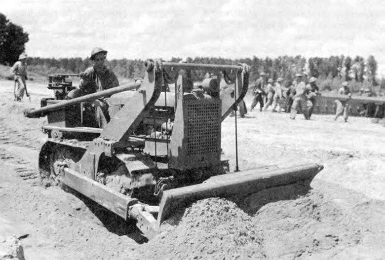
Bulldozer in operation, 3rd Army maneuver area, Louisiana, September 1941
In the fall of 1938, a 4½-ton tractor, complete with bulldozer and winch, was purchased from the Cleveland Tractor Company and turned over to the Engineer Board for tests by the 5th Engineers. The unit took it out on a muddy field to “doze,” lining up beside it for comparison a mule team and slip scraper operated by two men, and a 3-ton wheel scraper with six operators. The 4½-ton bulldozer with one operator moved sixteen times as much dirt as the animal-drawn scraper and four times as much as the 3-ton scraper. But the 5th Engineers were dissatisfied. They knew a heavier tractor would be even more efficient.
The Cleveland Tractor Company then offered its 7½-ton machine. The extra power in this unit caused the 5th Engineers to pronounce it definitely superior to the 4½-ton tractor. Noting that three other companies—Allis-Chalmers, International, and Caterpillar—could offer similar models, Capt. Gilbert E. Linkswiler of the Engineer Board recommended adoption of the 7½-ton medium dozer as standard equipment.
The increase in the weight of the tractors begot transportation problems. Some officers proposed that they be assigned to depots and brought forward as occasion demanded. Others argued that when dozers were needed they were needed badly, at once, and in quantity. Consequently, they wanted to carry with them enough to meet their maximum requirements at any one time. Linkswiler adopted a middle ground.
Sticking to the rule that troops should carry with them only that “habitually required,’’ he nevertheless found it “hard to imagine” general engineer units “engaged in work which could not be expedited by the use of a small number of tractors.” This small number (four to combat and general service regiments; two to squadrons and separate battalions) should be assigned as organizational equipment and with a reserve sufficient to meet emergencies to be held in depots. To carry out large-scale construction in rear areas, he recommended that army and communications zone depots stock 15-ton bulldozers. OCE approved this distribution in September 1939.8
Like the heavier tractors, the power shovels selected by the Military Division in 1937 and subsequently studied by the Engineer Board with a view to determining their distribution were multipurpose machines which could be converted into pile drivers or cranes for excavation, hammering, and lifting. Although Engineer officers agreed that such shovels would be needed in the combat zone, they were of different minds as to whether or not they should be issued as organizational equipment. According to the 1937 T/BA, combat regiments and squadrons were entitled to 7½-ton, ⅜-yard shovels; general service regiments and separate battalions to 15-ton, ¾-yard units. Presenting the case for issuing shovels directly to troops, one officer argued that “duties outlined for combat Engineers involve the acquisition, movement and distribution of immense quantities of materials. It is inconsistent to provide dump trucks for movement and distribution and to depend on manpower alone for the procurement and loading.” While a good many supported this position, there were more who agreed with the officer who believed that “in warfare of movement, the power shovel has no place in the column,” arguing that “division Engineers, to fulfill their front-line mission, must rely on their resourcefulness and ability to improvise, employing simple basic implements of all around usefulness, such as trucks and hand tools.” Baker, who weighed these views for the Engineer Board, advocated a reduction in the basis of issue. He favored assigning some 7½-ton shovels to the general service regiment because “the nature of its tasks should provide fairly continuous, profitable employment” for them. Since the need of other troops would be “more or less intermittent,” he recommended storing 7½-ton shovels in corps depots; 7½-ton and 15-ton units in army depots; and 15- and 20-ton units in the communications zone.9
In contrast to the difference of opinion on whether bulldozers and shovels were needed for the everyday operations of engineer troops, there was unanimity that air compressors were “almost indispensable.” The 105-cubic-foot, 7-ton compressor selected by the Military Division in 1937 furnished power for the operation of rock drills, pavement breakers, wood-boring machines, clay diggers, and saws. Although the Engineer Board favored the adoption of a lighter, more mobile compressor, the Development Branch held out for the heavier machines. The “105” was within the 7½-ton limit, was as mobile as any truck in a convoy, and, unlike the lighter machines,
Basic allowances: 1941
| Item | Combat Bn Inf Div | Armd Bn Armd Div | Sq Cav Div | Combat Regt Corps | Gen Sv Regt Corps | Separate Bn Corps |
| Air compressor | 3 | 8 | 2 | 8 | 8 | 4 |
| Bulldozer | 3 | 3 | 3 | 8 | 8 | 8 |
| Electric drill | 0 | 1 | 0 | 0 | 0 | 0 |
| Gasoline hammer | 3 | 7 | 3 | 3 | 2 | 2 |
| Gasoline saw | 9 | 9 | 0 | 18 | 0 | 0 |
| Road grader | 0 | 0 | 0 | 1 | 0 | 1 |
| Shovel, y-yard | 0 | 0 | 0 | 1 | 0 | 0 |
| Shovel, 3 -yard | 0 | 0 | 0 | 1 | 2 | 1 |
| Welding set | 1 | 3 | 1 | 2 | 2 | 2 |
| Cargo truck | 9 | 82 | 8 | 21 | 20 | 15 |
| Dump truck | 49 | 0 | 37 | 94 | 34 | 16 |
| Prime mover truck | 0 | 6 | 0 | 1 | 2 | 1 |
| Wrecker truck | 0 | 1 | 0 | 0 | 0 | 0 |
| Truck-mounted crane | 0 | 2 | 0 | 0 | 0 | 0 |
would furnish power for heavier and more varied attachments.10
The substitution of power machinery for hand tools, foreseen in the twenties and begun in earnest in the mid-thirties, had, by the fall of 1941, affected all engineer units having construction duties, as shown in table above.11
In Godfrey’s opinion this was a “fairly large amount” of machinery and trucks at the disposal of general engineer units with a field army. Engineer aviation units, organized in the summer of 1940, were to be equipped with power machinery in even greater number and variety.12
Equipping front-line units came first, both in theory and in the practical matter of allocation of funds. Aviation units excepted, the power machinery which engineer troops carried as organizational equipment did not represent the “construction plant” needed to carry out large-scale operations. For such tasks specialized machinery would be stocked in depots for issue upon requisition. The Engineers felt little compulsion to decide just what and how much specialized machinery would be required. Uncertainties inherent in the situation before Pearl Harbor had much to do with this attitude. With the theater of operations a matter of speculation, it was difficult to visualize the type and scale of future construction operations. Perhaps most important, the Engineers were confident they had sufficient knowledge to choose what was proper when called upon to plan for a specific construction operation. Only after Pearl Harbor were funds forthcoming to stock
construction machinery over and above that issued as organizational equipment.13
Until power machinery and other engineer equipment began to be bought in quantity the Engineers found it easy to postpone preparations for storage, distribution, service, and repair. It was not until the summer of 1940 therefore that a depot company and a shop company were activated. Their assignment to the technical supervision of the Engineer Board testified to the experimental nature of their organization and equipment. In the reorganization of 1939–40 the number of depot companies with a field army had been cut from four to one, whereas total personnel with a field army had been reduced by only one third. Hoping to bring about a partial restoration of the former balance, the commanding officer of the experimental depot company, with the backing of the Engineer Board, recommended increasing the company from 164 to 255 officers and men and furnishing it with mobile cranes, trucks, and tractors. Even so, the unit’s facilities would be insufficient for the servicing of heavy construction machinery. To service such machinery the Engineer Board recommended the formation of a special equipment company, and, in order to coordinate supply and maintenance, urged the creation of a park battalion to be composed of depot, dump truck, equipment, and shop companies.14
The particular organization proposed for the depot company was not adopted. Instead, in April 1941 the Engineer Board was asked to give the matter further study. The equipment company and the park battalion, approved about the same time, were also assigned to the board for study. Yet none of these units was to undergo as much experimentation as the shop company.15
The engineer shop company in the old Army had been charged both with making repairs and with simple manufacturing. In September 1940 1st Lt. Karl F. Eklund, commander of the newly activated 56th Shop Company, suggested that these tasks be handled by two different organizations as in other branches of the Army. He proposed that the repair company “be completely mobile and capable of taking the field as readily as the equipment it will have to maintain.” For general overhauling and manufacturing he advocated a less mobile base equipment company.16
Although a T/O for a mobile shop company was published in November 1940, OCE issued no other directives to guide the development of its organization and equipment, which continued at the board under the direction of Maj. C. Rodney Smith. Early in 1941 Smith presented a program which called for more funds and the use of the 56th Shop Company as a testing agency. Following approval of the broad outlines of his program, the board intensified research so that by August 1941 Smith had arrived
at a comprehensive estimate of the maintenance requirements of engineer troops. Heretofore, planning had been based upon one shop company to an army. Conscious of the tremendous increase in mechanical equipment, Smith proposed the assignment of one mobile third echelon shop to each corps, one mobile and one semi-mobile fourth echelon shop to each army, plus a group composed of both for GHQ reserve. On the basis of four field armies this meant forming twenty to thirty companies. Training of the personnel to fill these units was to be accomplished in factory schools until the spring of 1942, when an Engineer maintenance school with a capacity of 250 to 300 students would open. All this would have cost approximately six million dollars in 1942 and eight million in 1943.
The Engineer Board, while concurring generally in Smith’s program, suggested the use of both factory schools and the maintenance school and raised fiscal estimates somewhat.17 In OCE, Adcock pronounced this a “grandiose scheme” that would require “immediate additional supplemental appropriations, formation of several new units, and additional building construction at Belvoir.” Wartime experience was to prove Smith’s estimates modest, but it is nevertheless doubtful that approval for carrying them out could have been got from the General Staff and from the War Department Budget Office even had Adcock been willing to fight for them. In no mood to fight, Adcock directed O&T to submit “a suitable modification on a more practicable basis.”18
Instead of making more plans OCE settled for the time being upon the establishment of a standby organization. In September 1941 Kingman requested the immediate formation of two more shop companies, but even after receiving the War Department’s tentative approval the Engineers continued to fix minimum requirements at one mobile shop company per army and two base shop companies in GHQ reserve. There was to be no all-out program for the organization and equipment of maintenance and depot units until after Pearl Harbor.19
First things had to come first. It was impossible to accomplish everything at once. Fully aware of this fact, Kingman hailed the advent of a new Corps of Engineers as early as June 1940:
For years Engineer organizations have had to rely in great part upon man power and hand tools for the performance of their functions. ... Today we are far more fortunate. Recent appropriations have permitted the purchase of equipment which should enable our units to be modern in every respect. New multi-drive motor vehicles of the latest type are now being furnished our organizations. Up-to-date construction equipment is being supplied to our units, not for inspection but for training and use.
Moreover, he added, “modern bridge equipage is being delivered in quantities that will enable us to discard the type equipment used by General Grant’s army in the 1860s.”20
Strains on the Bridges
The importance of bridging in assuring the mobility of the new Army had been
repeatedly stressed by the Corps of Engineers. Reflecting on the blitzkrieg, Godfrey wrote:
Does an unfordable river block the advance? Perhaps a critical bridge may be seized by the dash of a few motorcyclists while the defenders are still hesitating to destroy it. But suppose the bridge is out, the opposite bank still held by the enemy. Time was when the army waited till night, crossed in the dark by raft or skiff, gained a foothold on the opposite bank ... later built a bridge. Now it appears that success may sometimes be achieved more speedily,—a crossing accomplished audaciously in fast motorboats, or a bridge built under fire.21
At the same time that the Engineers prophesied systematic destruction of bridges by the enemy they were aware of the inadequacy of their own bridging equipage and acknowledged that they were unprepared to keep pace with the enemy’s potential destructiveness.22
In this sense “keeping pace” meant speedy construction so that a river or ravine could not halt an Army column more than a few hours. To meet this requirement, the components of a military bridge had to be easily assembled. In another sense, “keeping pace” meant new designs to keep up with vehicular developments within the Army. As the Ordnance Department, at the behest of the using services, added weight to tanks, the Engineers had to increase the capacity of bridges. A third concern was with the mobility of the bridging equipment itself, so that ease of transportation became an integral part of design. These determining factors—speed of construction, capacity, and transportability—were often hard to reconcile. As capacity was increased the difficulties of transportation tended to multiply and the time consumed in erection to lengthen.
From one point of view the ideal military bridge was one consisting of parts which could be combined so as to carry either light or heavy loads over water or over ravines. The virtue of this type was that many situations could be met with the same basic structure and that troops would have to learn fewer erection techniques. Its drawbacks were that such a bridge would entail either the handling of unnecessarily heavy parts for a bridge of light capacity, or the use of a large number of light parts for a bridge of heavy capacity. From another point of view, the ideal was a bridge just strong enough to carry the heaviest load normally expected and designed especially for a water or a land crossing. This solution offered a saving in transportation space and construction time under some circumstances, but would result in a multiplicity of bridges.
The bridges the Engineers had to be prepared to provide were of three general types—assault, combat support, and line of communications. Because a floating or ponton bridge can be constructed more rapidly than a fixed bridge, an assault bridge is normally a ponton type. According to orthodox thinking the components of such bridges must be light enough and small enough to be put in place by hand. Fixed or floating, the structure must be capable of supporting the heaviest vehicle accompanying the initial attack. A combat support bridge, erected under less pressure for speed, may be floating or fixed and must be capable of supporting all combat elements. A line of communications bridge, intended to serve as a more or less permanent structure, is commonly a fixed bridge differing little from conventional civilian bridging.
In the summer of 1938, General Staff and
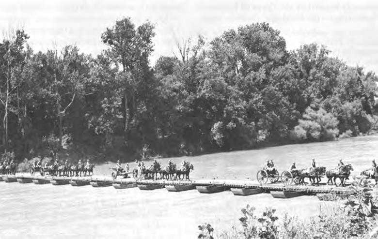
7½-ton ponton bridge over the Chattahoochee River near Ft. Benning, Ga., July 1939
Infantry officers informed Kingman that light tanks weighing between 10 and 11 tons and medium tanks weighing between 15 and 20 tons were being designed. On the basis of an understanding that light and medium tanks would operate together, bridge designers at the Engineer Board were attempting to develop a ponton bridge of 10-ton capacity which could be reinforced to carry 20. In this way all units of the Army could be served by one ponton bridge.
The Engineer Board did not have to start from scratch to develop a 10-ton ponton bridge. It had merely to modify a 7½-ton bridge which was in turn a modification of a Civil War model. All these bridges consisted of boats connected by wooden beams (balk) over which were laid planks (chess) to form a roadway. At most sites one or two trestles had to be placed inshore to provide supports for the span from the bank to the first boat. The aluminum boats of the 7½-ton bridge were 26 feet long and weighed about a thousand pounds. The modification recommended by the board in January 1938 and approved by OCE in June, brought the capacity of this bridge to 10 tons by enlarging the boats to 28 feet and increasing their weight by 450 pounds.23
During the following summer one such boat was tested. Despite its increased weight it proved easy to carry and maneuver. In
July 1939, meanwhile, eleven more boats were ordered in the expectation of assembling a complete bridge for testing. So certain was the Chief of Engineers that tests of the bridge would prove successful that he directed the Engineer Board “to give priority over every other activity” to finishing up drawings and specifications by Christmas 1939. Money to buy several units was expected in January. The board submitted the specifications on 22 December, and the same day asked the Chief of Ordnance to send a couple of medium tanks to the 70th Engineers who were to test the new bridge. While the commanding officer did not consider the tests altogether conclusive, they proved in general that the bridge would carry loads up to 12 tons provided the balk were strengthened. If reinforced by additional boats the bridge would take loads up to 20 tons. It thus appeared, as Kingman and the board had hoped, that the 10-ton bridge could supply assault bridging to division, corps, and army.24
For line of communications bridging the Engineers had for years relied on trestle or pile bridges built from ordinary commercial timbers and steel beams. Although eminently suitable for the rear areas these structures could not be erected in the limited time allowed for construction in combat support, much less during an assault.
The Engineer Board had therefore developed girder bridges with no intermediate trestles. The board did not believe that one fixed bridge should be made to serve both division and army. A light girder bridge would, like a ponton bridge, be used for an emergency crossing, then removed and replaced by a permanent bridge. A heavier girder bridge would be more permanent, spanning those gaps where the time consumed in constructing trestles would be inordinate, or where the piers of a partially destroyed bridge stood far apart. If the components of a light bridge were used to build a heavy one the span would have to be shortened considerably and more girders added, thus lengthening construction time. Both the H-10 and the H-20 portable steel bridges, as the girder bridges came to be called, were modeled after British bridges. They were so designed at the request of the Engineer Board by the firm of Sverdrup and Parcel of St. Louis, Missouri. The British H-10 bridge was a 64-foot plank roadway, supported by two steel girders formed of latticed box sections. The complete girder, with the aid of a roller and launching beam, was thrown across to the far shore at one time. The American bridge as designed by Sverdrup and Parcel in the spring of 1937 was somewhat heavier and somewhat shorter. There were five 12-foot lattice boxes to a girder, each weighing a little over a thousand pounds.
When the 5th Engineers tested this bridge in June 1938, they reported it stronger than expected—so strong that it could be lengthened to 72 feet by the addition of another section without reducing its 15-ton capacity. Moreover, a longer bridge could be built by adding girders—one for 96, and two for 108 feet. Its parts were sturdy and easily assembled. A crew of one officer and 41 experienced men could erect the normal 60-foot span in one hour, it was reported. This statement of the time required for construction of the H-10 bridge was, like all such estimates, subject to many qualifications.
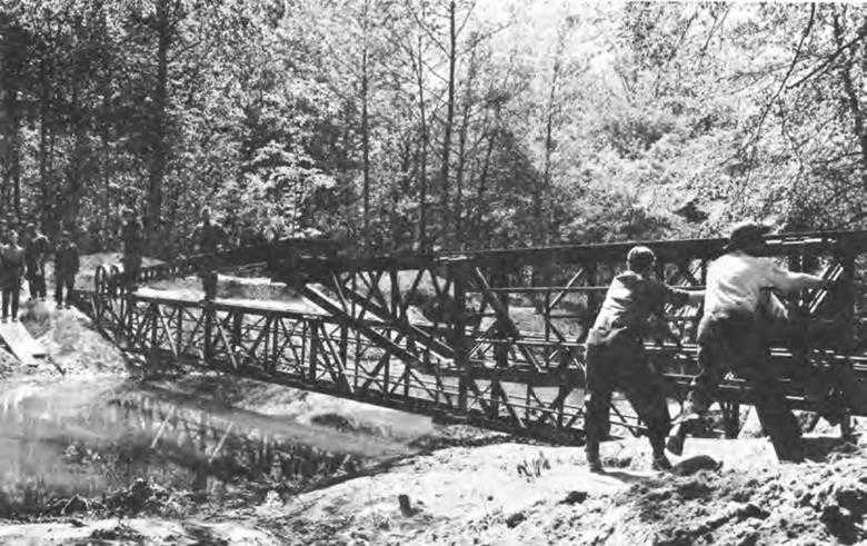
H-10 portable steel bridge being erected by men of the 4th and 5th Training Battalions, Ft. Belvoir, Va., May 1941
The length of time consumed in erecting any bridge varies greatly according to the skill of the builders, the character of the immediate terrain, and, for ponton bridges, the velocity of current.
The H-20 bridge had a span of 125 feet and was much like the H-10. It consisted of two girders made up of ten rectangular box sections 12½ feet long and two triangular end sections. Each section weighed 1,728 pounds, about 600 pounds more than a section of the H-10 bridge. Following tests in the summer of 1940 the 5th Engineers reported that the H-20 bridge carried its designed load and more up to 54 tons. Since the H-20 was not an assault bridge, machinery could be introduced into its construction. A crane unloaded the sections from trucks and maneuvered them into position for assembly into girders. The girders were moved into position by means of winches and cables strung through them so they could be pulled to the opposite shore. The 5th Engineers reported that with all equipment at the site an experienced work party could construct 100 feet of H-20 bridging in about three hours.25
In May 1940 the Corps of Engineers received some disquieting news. The Ordnance Department, strengthening its longstanding arguments for heavier tanks with
current information about the greater weight of German armor, had convinced the General Staff that the 15-ton medium tank was obsolete. The medium tank now projected would weigh about 25 tons. Plans were shaping up for a heavy tank weighing between 50 and 60 tons. The Engineers had been aware of Ordnance’s desire to develop heavier tanks. In 1927 they had standardized a 23-ton ponton bridge. The basic design of this bridge was the same as that of the 10-ton ponton; its capacity was greater because its pontons and other structural members were larger. Improvements made in the 10-ton ponton could be applied to the heavier bridge. The Engineer Board had been told to proceed with such improvements in the summer of 1939, provided time and personnel were available. Since time and personnel did not materialize, the Engineers were relatively unprepared when the General Staff gave Ordnance the signal to go ahead.26
Capt. Chester K. Harding, the officer most familiar with the 23-ton ponton bridge, believed that with slight modifications it would sustain from 25 to 30 tons and twice that amount when reinforced. On 29 May, Kingman, in conference with Godfrey, Adcock, Harding, and Baker, decided to increase the base capacity of the bridge to 25 tons by enlarging the boats. The board designed a new ponton in two weeks. It was 32 feet 9 inches long and weighed more than a ton, so that a truck-crane had to lift it. Still, no laws had been broken. Mechanical equipment was admissible in the construction of the 25-ton ponton bridge because official doctrine nominated tanks to support the infantry in river crossings.27 Normally, it was impossible for tanks to accompany the assaulting infantry. With tank support on the near shore, infantry moved across and established a bridgehead. Mechanical equipment could therefore be moved up after the infantry had dug in on the far shore. Once the bridge was erected, tanks would move across, pass in front of the infantry, and lead the assault.
Late in June, Kingman summed up the ponton bridging situation for the Chief of Staff:
a. The light ponton bridge, while designed for a 10-ton load, will carry a 13½-ton tank under favorable conditions.
b. The light ponton bridge when built “reinforced” (that is, with double the number of boats) is not an adequate bridge to carry a 25-ton medium tank. The bridge suitable for such a tank is our heavy ponton bridge, ... designed ... for a 25-ton loading.
…
e. As above clarified, the way seems clear, as to bridge capacities, for the development of a light tank not to exceed 13½ tons, and for a medium tank up to 25 tons.28
By September the weight of the medium tank was 28 tons, but if Harding’s calculations were correct the 25-ton bridge would take it.
OCE ordered eight 25-ton bridges on 29 August, and, five days later, recommended standardization. As yet there had been no tests, but so similar was this bridge to the
lighter one that little gamble was involved. Nevertheless, Schley insisted on a thorough workout early in 1941 when deliveries were expected.29
The committees assigned to the study of river crossing tactics at the research course conducted at the Engineer School in the fall of 1940 expressed considerable dissatisfaction with the bridging equipage available and urged that much could be learned from German practices. The emphasis on silent execution of the initial crossing should be sacrificed, they argued, in favor of the speed which could be attained by the use of storm boats:
The few seconds—or even minutes—of additional secrecy after the first wave leaves our shore is of relatively small value. ... In any case, the first burst of fire, when the enemy first discovers one of our boats, gives away the show; if by the use of fast motor boats we can be down his throat within seconds after he discovers us, we are better off than if we have to paddle laboriously to the shore in the face of fire.30
In addition to, or perhaps in place of, storm boats, rubber boats might be adopted.
As early as 1933 the Engineers had seen pictures of German troops using pneumatic floats for assault boats and ferries and in October 1939 O&T had forwarded to the Engineer Board a picture from a German newspaper which showed a raft built of pneumatic floats. It was not until the summer of 1940, however, when such pictures appeared in American newspapers and magazines, that the board was assigned a project to investigate the design and use of pneumatic floats. The advantages of such floats could be readily grasped. Rubber boats would be easier to handle and to move from place to place. In September 1940 the Bridging Section had called in three leading manufacturers of rubber boats, ordering from them models in several sizes, shapes, and materials. As the models were delivered and tested, both Capt. Frank S. Besson, Jr., and Capt. Clayton E. Mullins, who as commanding officer of Company B, 5th Engineers, carried out many tests for Besson, became more and more enthusiastic. They were therefore receptive to the suggestion that a light (5-ton) assault bridge be developed with rubber boats and treadways as its main components.31
The treadways were channels just wide enough to cradle the tires or tracks of a vehicle. Substituting them for standard balk and chess was another German idea which the board had begun to investigate and on which the committees urged further work. The committee on river crossing technique, of which Mullins was a member, favored their use in a 10-ton ferry mainly because they would distribute the weight of a vehicle and simplify loading. The committee on river crossing bridge tactics favored a new type of ponton bridge with treadways integrated into a system of trusses or the box girders of the H-10 fixed bridge, estimating that the approximately 2,500 separate operations which went into building the 10-ton ponton bridge would be cut to about 600. As a further contribution to speed, this
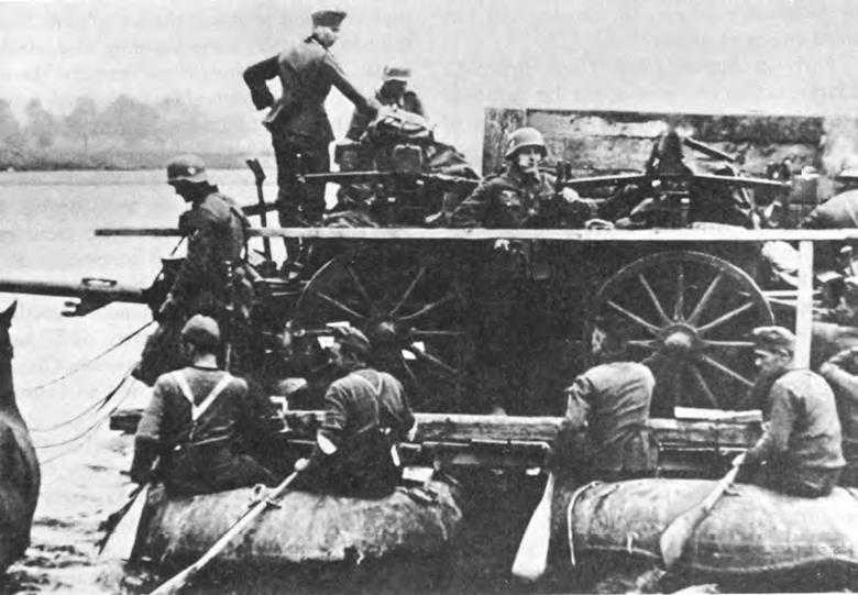
German raft built of pneumatic floats. This photograph appeared in an American publication in 1940
committee advocated the use of mechanical lifting devices.32
The use of treadways with H-10 girders was not favorably received in the O&T Section. Claterbos had seen a movie demonstrating construction of a bridge with H-10 girders and pontons, and the operation had seemed to him “a slow, cumbersome process.” Similarly, he believed “the use of trackways would also be slower than a well-organized bridge crew using the proper methods of erecting the bridge.”33
Meanwhile, pressures for changes in river crossing equipment came from Engineer officers attached to the Armored Force, which had been activated at Fort Knox in July 1940. With the ability to strike quickly and forcefully as its reason for being, the Armored Force had come to fear the possibility that frequent or extensive detours around rivers and mine fields might slow its movements. As part of a new organization, Engineer Armored Force officers were anxious to contribute ideas which would advance its future success, and were determined to match or surpass the aid given
by German engineers in assuring the forward sweep of armor.34
Early in August 1940, Capt. Bruce C. Clarke, acting engineer of the 1st Armored Division, furnished Godfrey with a list of suggested improvements in the equipment of the engineer armored battalion, stressing the inadequacy of the H-10 bridge. All elements of the Armored Force would be engaged in an encircling movement. Since the capacity of the H-10 bridge was insufficient to support the 25-ton tank this bridge would have to be supplanted by a structure that could. Godfrey agreed that the “H-10 portable bridge is certainly not the complete answer to our prayers” and assured Clarke that “the Engineer Board is now working on this problem” (presumably the H-20 bridge.)35 He also passed Clarke’s memorandum along to Kingman, who took this occasion to draw the Armored Force and the Engineer Board closer together. In a letter to the board inclosing Clarke’s memorandum, he emphasized the importance of assisting the Armored Force and directed representatives of the board to visit its headquarters at Fort Knox from time to time.
Three days after receiving Kingman’s message, Baker, the board’s executive, and Leif J. Sverdrup of the designing firm, were at Fort Knox. The engineer armored battalion was authorized one 125-foot unit of H-20 bridge; one 72-foot unit of H-10; 300 feet of portable trestle; one 25-ton ponton bridge; and two portable tank ferries of 30-ton capacity, an extremely long bridge train for a mobile unit. In August 1940, the unit had only the trestle, an H-10, and a 10-ton ponton bridge. Baker found the Armored Force engineers convinced that the bridging authorized was unsuitable and that “perhaps some special bridging equipment would be needed.” As they repeated to Baker the complaints contained in Clarke’s memorandum and added some others, he sought to reassure them. When asked for portable rafts, he told them to use the 10- and 25-ton ponton equipage, adding that the board was considering the possibility of a special barge. When Clarke expressed the belief that the trestle bridging assigned would not support the medium tank, Baker suggested that it be strengthened with decking and trestles of the 25-ton ponton bridge. Objecting that standard wooden decking was too weak to carry tanks and yet too heavy to handle expeditiously, Clarke suggested that Z-irons be used to form a treadway.
The idea of using treadways had occurred also to Maj. Thomas H. Stanley, commanding officer of the 16th Engineer Armored Battalion of the 1st Armored Division, who had gone so far as to work up some rough drawings. Treadways were not new to Baker either, since he was familiar
with the investigations under way at the Engineer Board. Although doubting their value as a substitute for decking, he readily agreed to ship some treadways to the Armored Force engineers since he believed that “every effort should be made to get a bridge which will be more nearly what they want.”36
To provide such a bridge for the Armored Force engineers imposed a considerable burden on the Bridging Section at the Engineer Board which already had more projects than employees. Captain Baker unburdened his troubles to Sverdrup on 18 September:
Seems as if everyone, particularly the armored force people, is demanding longer, lighter, more quickly placed, greater capacity bridges. So we have got to get something out soon or else show them it can’t be done. Some of our people have become more enthusiastic about ... a bridge with longer sections, with special erecting equipment, and which can be more quickly placed than the H-20. (However, we are well pleased with the H-20 and, as I told you, the Chief’s Office is going to advertise for some of them as soon as possible.)37
Besson, having had more experience with the H-20 bridge, was not so pleased. He noted that it was “considerably heavier and harder to erect than the H-10 bridge,” being “a deliberate operation requiring the better part of one day to get it in.” It was his “personal opinion ... definitely not an official Board opinion,” that “the H-20 bridge is not suitable for forward combat echelons and is a heavy installation for the supply echelon.”38
The Armored Force engineers at Fort Knox also remained dissatisfied. During the fall and winter of 1940, Stanley, Clarke, and Lt. Col. Lunsford E. Oliver, Engineer of I Armored Corps, speculated as to how they could improve their bridging. Clarke, in particular, was most anxious to develop faster means of spanning narrow streams and gullys than was possible by use of the timber trestle bridge. To that end he urged that treadways be laid across the stronger prefabricated steel trestles issued as part of the ponton bridge equipage. Experiments with this variation, while not conclusive, were encouraging. Although at the board Baker considered the project important enough to be pushed, he hesitated when it came to “special trestles and special flooring.” Yet he promised shipment of about 50 feet of treadway to Fort Knox by the end of January. In the midst of these experiments Clarke was reassigned, but Oliver and Stanley continued to apply pressure on Fort Belvoir.
These two officers were becoming increasingly concerned over the development of a suitable floating bridge because they believed the 25-ton ponton bridge would be too difficult to transport and would take too long to erect. Their opinion was based on observations of the 10-ton bridge, since they had been issued no other, but they knew the same disadvantages would be exaggerated in the heavier structure.
The climax to their dissatisfaction occurred one night early in December 1940 when the bridge company was putting on a night show for Newsweek cameramen. After the bridge had been erected a tank was backed on and the photographers took “a few faked ‘action’ shots.” When the driver tried to move forward off the bridge, the
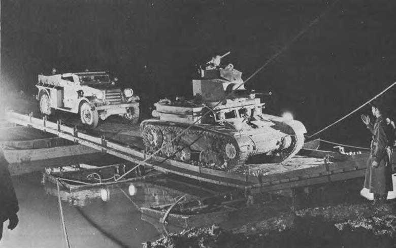
10-ton Ponton bridge at Fort Knox, KY. Note tank touching curb rail and partial submergence of pontons. This photograph appeared in Newsweek, 23 December 1940
tank stalled. A bulldozer brought to the rescue only succeeded in getting it as far as the hinge span, at which point the end ponton sank to the bottom of Salt River. Stanley hastened off to get a wrecker truck, leaving strict orders to let everything remain as it was. When he returned, he found most of the bridge under water. Another officer had decided to back up the tank. Only in the process of lifting the tank off the bottom of the river did Stanley discover it was not a 9-ton as he had been led to believe, but a new 13-ton model. The added weight, together with the fact that the driver had got off center when he backed up, explained the accident.
This incident determined Oliver and Stanley to pursue Stanley’s idea of using steel treadways instead of the standard wooden flooring. On the 27th of December, Stanley wrote Godfrey about the accident, concluding “that the 10-ton bridge should be used for 13-ton tank loads only in an emergency, and then only with every precaution to keep the load centered on the roadway. ... Perhaps the Engineer Board has already considered this problem,” he continued, “but it would seem possible to design treadways for the ponton equipage, both light and heavy.” He suggested dimensions for the treadways and a method of joining them together.39
The treadways would probably be too heavy to put in place by manpower, but the Armored Force was a completely motorized
and mechanized outfit and its engineers could see no objection to dependence upon machinery for division bridging as did the Engineer Board and the Military Division in Washington. Oliver and Stanley believed the treadways would speed up construction because fewer parts had to be fitted together, would sustain more weight by distributing the load over more pontons, and would keep the driver on center by means of their channels.
On 2 January 1941, Oliver wrote Besson about the idea and enclosed a rough drawing. When the letter arrived, the board was already prepared to ship the treadways intended as flooring for the trestle bridge. Presumably Stanley could try them out on pontons if he wished. Whatever the reason, Fort Knox heard nothing from Fort Belvoir.
The treadways furnished by the board were modeled closely on the German trackways and were not at all what Stanley had in mind. Conforming to official doctrine, they were light enough to be handled without the aid of machinery. They were flat. Stanley wanted curbs to keep the vehicles from sliding sideways. They were in short 12-foot sections, and were so narrow they offered no leeway for vehicles of different widths.
On 11 February, Oliver, accompanied by Stanley, arrived at Fort Belvoir to witness tests of a ferry which utilized treadways. Again they found fault with the treadways which were similar to those furnished them for the trestle bridge. Again they explained how they wished the treadways designed and expounded their ideas for using them as decking for ponton as well as for trestle bridging. But the two left Fort Belvoir convinced that no one there had the time or the interest to pursue the work with the speed they believed essential. They determined to carry out the entire project at Fort Knox.
Since neither Oliver nor Stanley was free to work up a finished design, they turned the idea over to 1st Lt. W. Eugene Cowley, a motor officer attached to the 16th, who was a mechanical designer by profession. Cowley planned for curbed treads, 15 feet long, 33 inches wide, spaced 39 inches apart, which would accommodate all double tracked vehicles. He evolved a joint for the sections, flexible enough not to overstress the treadways, yet strong and rigid enough so that loads would be distributed over several pontons at once, thus providing the continuous beam action that Stanley and Oliver feared would prove most difficult to achieve.
Although Oliver had money enough to order some treadways fabricated to Cowley’s design, he preferred to clear the matter with OCE, explaining his point of view thus to Besson:
There is a well-equipped shop in Louisville which is willing to do the work for us and I believe we can secure much more rapid results than we can if you do it for us, because of the fact that we can quickly carry out tests and can immediately have changes made as indicated. Please do not consider that we are in any way dissatisfied with the work of the Engineer Board for we are not. You are just so far away from us that quick results are difficult to attain, and we know of no more valuable use for the funds I mentioned as available.40
The board objected. Admitted that Armored Force engineers knew their own problems better and could concentrate all their
time and talent on solving them. Yet it was quite a gamble, the board argued, to transfer responsibility to an officer or command apt to be transient and apt to ignore the interrelationship of plans, specifications, and procurement which the board so well understood. Responsibility for new designs should remain centered in a permanent agency. Baker recommended to Chorpening that Armored Force engineers either submit their designs for approval or detail an officer to Belvoir. The board was not standing still. The old treadways had been redesigned and a test unit would be delivered to Knox by mid-March. At the same time, the board professed itself agreeable to Oliver’s buying treadways in Louisville. What it did insist upon was an “opportunity to check ... work [done at Fort Knox] from the point of view of its broader experience.”41
On 5 March, before Oliver received any of these objections, he arrived in Washington with Cowley’s plans in his briefcase. When Kingman told him he was opposed to surrendering the board’s authority, Oliver argued for complete freedom. Was Kingman willing to accept responsibility for failure of Armored Force engineers to carry out their mission for lack of suitable bridges? Kingman finally said no, and gave Oliver permission to go ahead. Arriving back at headquarters, Oliver placed an order with the Louisville firm for enough treadway decking to span Salt River.42
It was precisely at this time, when the engineers at Knox had the freest hand in carrying out their ideas, that the engineers at Belvoir did most to help them. The Engineer Board had been pushing the development of pneumatic floats vigorously. In March 1941, before Armored Force engineers had received the treadways from Louisville, the board sent some small pneumatic floats to Knox. Receipt of these floats brought about a radical change in the conception of the Armored Force bridge. On 25 April Oliver wrote Baker:
I have thought of our assault boats as being superior to the rubber boats, but have changed my mind. ... As a matter of fact, Stanley and I are ahead of you now and are thinking of the use of the large rubber boats, in conjunction with the treadways we are developing here.
The light, easily transported floats would replace the bulky 25-ton pontons. Oliver asked the Engineer Board to supply larger pneumatic floats, and Cowley was put to work designing “saddles” for the treadways to rest upon.43
Early in June, a treadway bridge built with 25-ton pontons and a treadway raft built with floats were demonstrated at Fort Knox. This demonstration settled for all practical purposes the question of bridging for the Armored Force. More treads, floats, and truck cranes to handle the treadways were immediately ordered. On 22 September 1941, OCE recommended that all fixed and floating bridging and the 30-ton ferry be deleted from the Armored Corps T/BA,
and the steel treadway bridge be substituted. The bridge train was reduced to five sixths its former size. Furthermore the speed of construction of the treadway bridge as compared with the standard ponton was striking. In December 1941, the 17th Engineer Armored Battalion sponsored a demonstration at Fort Benning, Georgia, setting up uniform conditions for purposes of comparison. A 315-foot pneumatic-float treadway bridge of 30-ton capacity was built across the Chattahoochee River by 154 trained officers and men from the 17th in 2½ hours. It took 245 men of the 87th Engineer Heavy Ponton Battalion 4½ hours to put across a 25-ton ponton bridge 328 feet long.
A wave of triumph swept through the engineer contingent at Fort Knox. The imagination of Stanley, the persistence of Oliver, and the ingenuity of Cowley had been rewarded in full measure. Among the observers from the Engineer Board, Besson and Mullins could point to the pneumatic floats and share credit for the achievement. Yet these two shared also Chorpening’s misgiving as he turned and said, “We’ve adopted something without a real service test.” Otherwise the remark was drowned out in the tide of enthusiasm. Less than a year later it was to prove prophetic.44
Good as the treadway bridge looked in December 1941 no one suggested that it be universally adopted. The Armored Force had got what it wanted. What it had was not desired elsewhere. This remained true even as armor came to be accepted as an accompaniment of infantry. The treadway bridge was expensive and less durable than standard ponton bridges. Perhaps most important—speedy construction of bridges was not considered as essential by infantry as by armored divisions, for the lightly equipped assault infantry could be ferried across.
By December 1941 the Engineer Board had completed tests of light infantry support rafts and bridging similar to that which had speeded German river crossings. The new equipment was far more efficient for ferrying operations than the standard ponton equipage relied on previously. Constructed of plywood half-boats and treadways or pneumatic floats supporting standard balk and chess, these rafts and bridges had a capacity somewhat under 10 tons and took up relatively little transport space. Their adoption enabled the Engineers to reduce the amount of bridging assigned to the field army and the number of light ponton units from four to two.45
Provision of heavier bridges was conspicuously less successful. The long-sustained hopes that the 25-ton ponton would serve were dashed shortly after delivery of the pilot model of the Sherman medium tank. The Sherman weighed 33 tons. Tests of the 25-ton bridge showed it could not carry the new tank unless reinforced, and that the ultimate reinforced capacity of the bridge was about 35 tons. By November the board was working to raise the base capacity of the 25-ton ponton to 31 tons so that medium tanks accompanying divisional units could pass over it.46
The increasing weight of tanks was also causing trouble with fixed bridges. While more girders could be added to the H-10 or
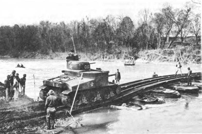
Pneumatic-float treadway bridge built across the Chattahoochee River, December 1941. Medium tank crossing the bridge is an M3A3, weighing approximately 30 tons
the H-20 or their spans shortened in order to make them sustain heavier loads, such alterations led to a less efficient piece of equipment. Another general drawback of both these bridges was the heaviness and bulkiness of their components, which made them difficult to transport and, in the case of the H-20, slow to erect.47
But more serious than the difficulties the Engineers faced in keeping up with increasing weights was the manner in which they had solved their basic problem, namely, by providing a multiplicity of bridges. The British, by contrast, had been working toward the provision of all-purpose equipage, and by the summer of 1941 were ready to begin production of the Bailey bridge, so called for its designer, Sir Donald Coleman Bailey. The Bailey was strikingly different from any American military bridge because most of its structural members were above rather than beneath its roadway. The Bailey’s main support was a continuous truss on either side of the roadway, joined beneath by transoms. Unlike the box sections of the H-10 and H-20, the Bailey’s sections which, joined together, formed the truss, were flat panels. They were much lighter—a Bailey panel weighed 600 pounds or about half that of a section of H-10 bridge. Although the Bailey could be handled and transported more easily because
of its “knocked-down” sections, more parts had to be fitted together before launching than in the H-10 or H-20 bridges. It was reported that a British crew of 53 men built an 80-foot, 21-ton capacity Bailey in 2 hours and 20 minutes, taking slightly more time than for an H-10 and much less than for an H-20. The great advantage of the Bailey was its adaptability to various loads. For example, a certain number of panels fitted together would take 28 tons over a 60-foot span; by adding more panels both alongside and above one another, it would take this weight over a 170-foot span. It could be constructed to carry as much as 78 tons over a 120-foot span. The Americans had no bridge that would take so much weight, let alone one that was capable of meeting such a variety of weights and situations. As a further selling point, there was a great deal to be gained if British and Americans standardized on the same bridge. Because the Bailey could be erected as a single span over narrow crossings, as a multiple span with trestles over wider ones, and because there was good reason to believe that it could be floated on pontons, it appeared an “all-purpose” bridge had been found.48
In the summer of 1940 Besson returned from England with working drawings of the Bailey. The Engineer Board asked Sverdrup and Parcel to use them, but to modify the design sufficiently to make the bridge conform to the practices of American rolling mills. Three weeks after Pearl Harbor Chorpening wrote G-4 asking permission to spend $50,000 to buy one Bailey bridge. Tests would show whether the Bailey was versatile enough to replace some or all of the bridges on which the Corps of Engineers had expended so much effort during the prewar years.49
Although the design and selection of bridging equipage received most attention by far in the period before Pearl Harbor, the Corps of Engineers was also concerned with the mobility of ponton units and with the question of whether ponton troops, heretofore simply caretakers, should not be charged also with construction of bridges. In the spring of 1940 the advent of heavier tanks made the activation of a heavy ponton battalion imperative. Authorized in June, the heavy ponton battalion was provided with up-to-date trucks and trailers which reduced the length of its train and enabled it to keep up with armored units.50
According to doctrine, ponton troops were to deliver bridging equipage and provide instruction and technical advice to the general units which were charged with the actual construction. Ponton units were responsible for maintaining and dismantling
the bridge. After experience in the 1940 maneuvers the commanding officer of the 70th Light Ponton Company suggested that the unit’s mobility be increased and that it be made less of a depot outfit. He proposed that all its footbridges and assault boats be eliminated and that it be provided with its own transportation. Toward the end of 1940 OCE adopted these recommendations in part. The light ponton company was furnished its own trailers and some of its footbridges and assault boats were redistributed to corps engineers.51
During the fall 1940 research course at the Engineer School, the committees on river crossings recommended the assignment of bridge building to ponton units and corps engineers, the activities of divisional engineers to be limited to the assault wave. Specially trained corps engineer units would take over for erection of light ponton bridges. Heavy ponton bridges would be built by heavy ponton battalions, with the aid of personnel from general units.52 Early in 1941, when friction developed between the commanders of a combat regiment and a light ponton company at Fort Benning, the issue was raised more specifically. Kingman and Godfrey backed the regimental commander’s view that the light ponton company was primarily a transportation and care-taking unit. In January 1941 the mission of the heavy ponton battalion had been modified to permit it to construct heavy bridges “under certain circumstances,” but this declaration of policy did not settle the issue. It was to arise again during maneuvers in 1941 and after Pearl Harbor.53
The engineer armored battalion, with its bridge company, represented an exception to the general doctrine and was subject to criticism even among armored engineers themselves. In March 1941 the research committee dealing with the mission and training of this unit noted that the bridge company did not have sufficient equipment for a major operation, that it deprived the battalion of working personnel for other missions, that it added to the battalion’s road space, and that there was considerable terrain where it would not be needed. The committee urged the elimination of the bridge company and its replacement by a lettered company.54 These recommendations came in the midst of development of the steel treadway bridge, and, as Clarke later recalled, the bridge company “was built around equipment that was not in existence, but equipment we hoped ultimately to get. The purpose of it was to establish a bridge organization that would guide our thinking and development.”55 When the commandant of the Engineer School endorsed the proposal for eliminating the bridge company, the Armored Force argued for its retention, at least for the time being. The
need for additional troops in the engineer armored battalion could not be gainsaid, but this deficiency, the Armored Force emphasized, should not be confused with the need for bridging in close support of armor—a fact which foreign armies had recognized. Until a heavy ponton company and a fully motorized company having 500 feet of portable bridge became available for normal attachment to each armored division, the engineer armored battalion was not ready for a change. Nor did change come until well after Pearl Harbor.56
Passage of Artificial Obstacles
With bridging and with construction machinery the Corps of Engineers prepared to overcome the enemy’s exploitation of natural obstacles. Encouraged by the feats of German engineers in the passage of mine fields and in the reduction of deliberate fortifications, the Corps gave thought to the execution of these duties, but before Pearl Harbor the amount of theorizing exceeded the amount of down-to-earth testing of doctrine and equipment. The first attempt to compare the effectiveness of various artificial obstacles was made at the request of the Engineer Board in 1937 and 1938 by a number of engineer troop units. Their study included land mines, antitank ditches, wooden piling, wire rolls, and road craters. All of these, it was concluded, would provide adequate barriers to tanks and trucks if properly and strategically placed.57
The second evaluation of the effectiveness of obstacles resulted from the research course at the Engineer School. The committee on obstacles stated baldly that “antitank mines alone are likely to constitute an effective obstacle” and that “other obstacles serve merely to augment the mine or replace it if normal supply fails.” The superiority of the land mine over all other obstacles was not only evident in its crippling effect upon vehicles, but in the ease with which it could be transported, put in place, and concealed. The heavy steel and concrete obstacles which had been employed as part of the fortified lines of the continental countries required extensive fabrication and thousands of man-hours in placement. Such deliberate fortifications might be installed at Panama or Hawaii but had no place in a mobile situation. Craters and ditches, abatis, log obstacles, and wire rolls, the committee concluded, were suitable for installation in the field and were more or less effective, particularly if used in conjunction with mines.58
The technical aspects of land mines were matters in which responsibilities were divided between the Ordnance Department and the Corps of Engineers. Ordnance had the duty of developing the mines themselves while the Engineers were to develop means of detecting them. Both services were involved in the techniques and equipment for clearing them out of the way. In April 1940 the Engineer Board had been directed to investigate means for the detection, destruction, and removal of antitank mines, but
during the following months the pressure of other work pushed the project into the background. Concerted efforts to develop a detector finally got under way in earnest in the fall of 1940.
The fact that all mines known to exist in 1940 were encased in metal simplified greatly the development of a mechanism which would signal the presence of a mine. In fact, there were on the market a number of “detectors” which had been used for such diverse purposes as the discovery of metal objects in the mattresses of convicts and the location of mineral deposits. Moreover, the British, French, and German Armies were equipped with mine detectors with which the Engineers were more or less familiar. But while commercial detectors were useful as a starting point, none could be adopted for military purposes without modification, and the Engineers’ attitude toward the adoption of a detector in use by a foreign army was the cautious one of testing with the desire to improve upon it.
On 3 September 1940 the Engineers asked the National Defense Research Committee (NDRC) for assistance in the development of a metallic mine detector. The device, wrote Godfrey, must be capable of detecting a steel plate ⅛ of an inch thick, 10 inches square, buried 18 inches below the surface of the ground. The indicator must be simple so that personnel with little or no scientific training could read it. It should be rugged as well as light. Referral of this investigation to the NDRC did not result in cessation of the Engineer Board’s activity. On the contrary, as personnel became available shortly thereafter, the board was able to devote more time and effort to the subject than before. For the better part of 1941 the NDRC and the Engineer Board sponsored parallel investigations.
After canvassing the market, Capt. George A. Rote, who was in charge of the investigation at the board, purchased seven of the most promising commercial detectors. Six of this group operated on a radio-frequency principle. The seventh, a device which Hedden Metal Locators, Inc., of Miami, Florida, demonstrated in February 1941, appealed particularly to Rote because it operated on audio-frequency. It was relatively light and possessed about the degree of sensitivity required. By the summer of 1941 Rote had settled upon the Hedden instrument as the starting point for further development.
Meanwhile the NDRC had contracted with the Hazeltine Service Corporation, a radio research establishment located at Little Neck, New York. Hazeltine produced a detector which was delivered to Fort Belvoir on 1 August. When lined up with the Hedden detector which the board had modified, the Hazeltine model had the disadvantage of being heavier and bulkier. The board’s investigators indicated their preference for the Hedden-type detector, but realized that the Hedden company lacked facilities for quickly carrying out the many refinements required for quantity production. Hazeltine, on the other hand, was eminently equipped to take on this job, and did so following a conference at Fort Belvoir early in August.
The operator of SCR-625 (as the Hedden-Engineer Board-Hazeltine mine detector came to be called after the nomenclature of the Signal Corps which procured it) carried in his hand an exploring rod six feet long at the lower end of which was a pie-shaped search coil containing both transmitting and receiving elements. Batteries and an amplifier were carried in a haversack strapped to the operator’s side.
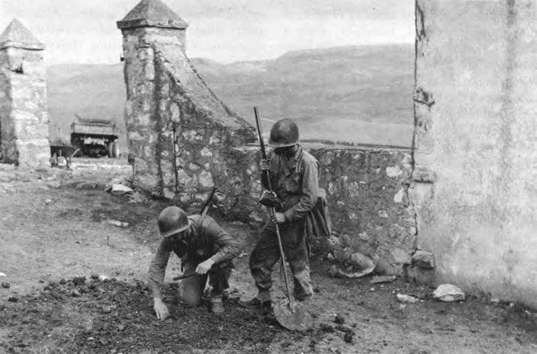
SCR-625 mine detector in use in North Africa, April 1943
A resonator was attached to his shoulder.
The presence of metal in the vicinity of the search coil produced a signal which was amplified into a warning sound in the resonator. SCR-625 would detect a metallic mine buried 6 to 12 inches. Its penetration was thus less than the 18-inch depth Godfrey had specified, but in practice few mines were buried deeper than a foot. By February 1942 the Engineers were in a position to standardize this set.59
The development of the portable mine detector was the outstanding Engineer contribution to the passage of artificial obstacles made during the defense period. Other studies by the Engineer Board and the Engineer School, notably the testing of various means of breaching shellproof and splinter-proof weapons emplacements, resulted in some additional knowledge of demolitions techniques, but the inauguration of a comprehensive program for determining the most efficient means of reducing obstacles did not occur until 1942.60
Equipment for Aviation Engineers
By December 1941 the Engineers had accomplished the fundamental changes
dictated by the new-found mobility of ground force units. They had, moreover, made a similar adjustment to the most mobile component of the new Army—the Air Corps. When, in the fall of 1939, the General Staff approached the Engineers about their service with the Air Corps, Kingman had noted that special equipment, as well as special troops, would be required for the construction of airfields. Seven months later, when the 21st Engineer Aviation Regiment became the first engineer unit attached to the Air Corps, its troops were assigned only the basic construction machinery issued to the general service regiment. Although Davison, commanding the 21st just before his assignment as Air Engineer, had given some thought to the special requirements of this new unit, it fell to Chorpening as chief of OCE’s Development Branch, to make an immediate selection for procurement. He invited a construction contractor friend of West Point days home for the weekend. Together, they drew up a list of construction machinery which Kingman approved late in July.61
In making his selections Chorpening assumed that aviation regiments would build advance airdromes twenty to seventy miles behind the front and that such troops would remain in one place for a relatively long period of time. Because aviation engineers would not have to keep up with advance columns and because they had to be prepared to deal with all sorts of climatic and soil conditions, Chorpening assigned to them a great variety of the heavier, more efficient types of machinery. For grading and transporting fill, aviation units were equipped with four sizes of tractors; disk and tractor plows; rubber-tired, sheepsfoot, and tandem rollers; large carrying scrapers and shovels with draglines; and road graders and leaning wheel graders. Although aware that paving operations would be time-consuming, Chorpening thought that aviation engineers should be equipped to build bituminous or concrete runways if the ground encountered did not offer sufficient bearing capacity. For such work aviation engineers were to get concrete and road material mixers and asphalt and emulsion distributors. In all, aviation engineers were to receive twenty-six pieces of “special” machinery and were to come closer to carrying a “construction plant” than any other engineer unit. Although agreeing wholeheartedly with Chorpening’s selection of tractors, scrapers, and other grading machinery, Davison, Smyser, and other officers with the Air Corps were becoming convinced that hard-surfaced runways were a luxury that aviation engineers could not afford. They consequently questioned the need for paving machinery.62 The planes in existence at the time the Engineers were told to prepare for their mission with the Air Corps were so light that sod fields would suffice for advance bases. Runways for bombers based in rear areas could be built like standard highways. These plans for simple construction were almost obsolete as soon as made, for the Air Corps was even then designing heavier planes which called for runways of greater bearing capacity. Constructing runways at the front and more
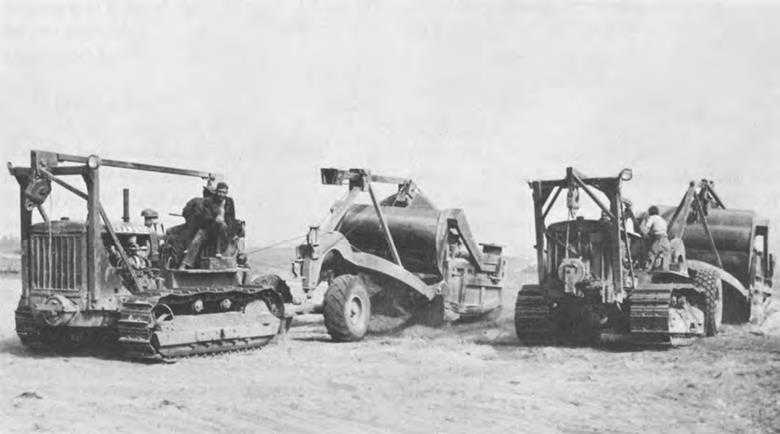
Aviation engineer equipment. Road scrapers towed by tractors are grading for a landing field, 1st Army maneuvers, North Carolina, October 1941
elaborate ones farther back, as the planes being contemplated in 1939 dictated, would take a long time—long enough to interfere seriously with the striking power of the air arm.63
No wonder then that the Air Corps expressed immediate interest in news that the British and French were laying down portable steel mats as a substitute for hard-surfaced runways. In December 1939, the Air Corps asked the Engineers to develop a similar landing mat. Since practically nothing was known about the subject, the two services agreed that the Engineers would attempt to get more information from abroad, would canvass the American market for likely materials, and, after conducting field tests with loaded trucks, choose the most promising types for service tests with planes. To carry out this program, the Air Corps set aside $30,000 of fiscal year 1940 funds—$5,000 for preliminary and $25,000 for service tests. The goal was a suitable mat by 1 July 1940.64
The Chief of Engineers assigned the supervision of this investigation to the Construction Section, OCE, whose chief was Lt. Col. George Mayo. Responsibility for testing was placed upon Maj. William N. Thomas, Jr., at that time the only Engineer officer with GHQ Air Force, who thus
assumed personally the role ordinarily played by the Engineer Board. Mayo and Thomas did not wait for reports from abroad but immediately sought suggestions from Clarence E. Meissner, the Washington representative of the United States Steel Corporation. On 18 December 1939, they met with Meissner, his colleague, Charles W. Meyers, of the American Steel and Wire Company, and two representatives from the Office of the Chief of the Air Corps. Meyers exhibited samples of a rectangular wire mesh which he believed would prove superior to the chevron grid in use abroad. In February 1940, the Engineers ordered enough rectangular grid for field tests, which were held in late March.
Far from providing the firm base necessary, the rectangular grid showed serious weaknesses: connectors broke, anchors failed, furrows and depressions appeared. Although Thomas recommended that efforts be made to correct these deficiencies, he also began to look about for something else. On 4 April 1940 he and several representatives of the steel industry met in Mayo’s office. Pointing out that the rolling mills were piled up with orders while the strip mills were not busy, Gerald G. Greulich of Carnegie-Illinois Steel Corporation suggested thin steel plates as an alternative to grid and volunteered to design a “plank” type mat and connectors.
Greulich’s design had progressed to the ordering stage by the first of May, when Maj. Gen. Henry H. Arnold, Chief of the Air Corps, began to express impatience. “The requirements,” he stated, “may be divided into two separate categories: First, pursuit and observation, i.e., light weight types. Second, bombardment, i.e., heavy load types.” It seemed possible to him that “if no delays are incurred and if this project is pushed that some concrete decision can be arrived at by the first of the Fiscal Year 1941.”65
In replying Mayo outlined general plans but avoided specific commitments. As to requirements, the investigation had already led to the conclusion that they were divided into “two categories” so that “study will go forward under these headings.” He could also report that “within the past week steps have been taken which will insure that all speed consistent with the production of a satisfactory solution will be made.” Specifically, these steps were the assignment of the project to the Engineer Board which would hereafter work in close alliance with the 21st Engineer Aviation Regiment and its commanding officer, Davison, both on the development of the mats themselves and on techniques for their camouflage. As to a product by the first of July, Mayo made no promises. Indeed so far was he from expecting the deadline to be met that he sought the Air Corps’ permission to divert $25,000 of the $30,000 allotted to the development of landing mats to the purchase of construction machinery for the 21st Engineers. If this plan were approved, he proposed to set aside an equivalent amount from Engineer funds to take care of the tests of landing mats which would take place during the coming months.66
Arnold’s answer to the request for transfer of funds was emphatic. “The most recent information from operations now in progress abroad,” he wrote, “indicates that permanent runways are out of the question in modern warfare,” causing “the development
of landing and take-off mats to assume the highest possible priority.” Several landing mats were needed immediately in Puerto Rico. “It is strongly recommended,” he concluded with some sarcasm, “that the policy be followed of supplying something usable and suitable at once, rather than reaching ultimate perfection at a later and undetermined date.”67
Kingman was quick to assure Arnold the Engineers were making progress. Stronger connecting links were being procured for the rectangular grid; interlocking steel plates had been ordered; mats similar to those used in Europe were being investigated. But, he emphasized, “The Chief of Engineers is anxious to avoid a commitment to a portable landing mat without reasonably conclusive tests.”68
On 4 June Arnold was on the telephone demanding a report from Schley. Despite strong doubts that anything “usable and suitable” would result, the Engineers felt compelled to produce something. After a conference with Kingman on 14 June, Mayo directed the board to submit a report by 1 July. Kingman would have none of Mayo’s arguments that the chevron grid mat would prove worthless for any but the lightest aircraft. With full knowledge that neither this type nor the steel plank mat had been given field tests, Kingman ordered Mayo to buy enough of both for service testing. Although by mid-June this display of activity led an Air Corps officer to assure Arnold that “there will be no further delay in carrying forth this project to a rapid conclusion,” the situation hardly warranted the hope that the 1 July deadline would be met.69
The deadline was met, however—at least to the satisfaction of the Air Corps. On 28 June, when the steel plank mat was submitted to tests under truck loads, Maj. Charles Y. Banfill, the Air Corps’ representative at the Engineer Board, concluded that something “usable and suitable” had been found. “The tests, by no means exhaustive,” he wrote the board, “indicated to me that the planking, laid on properly prepared surface would prove a suitable support for landing and takeoff of any airplane now in service.” He urged that the Air Corps be advised to go ahead and buy whatever quantity it needed while the board proceeded with tests of the steel planking and with their investigation of other promising materials.70
With but one reservation, the Engineers were happy to endorse this statement. On 1 July, Adcock, the Executive Officer, OCE, reported to Arnold:
I feel that the tests [of the plank mat] ... offer reasonable basis for the conclusion that a usable and suitable type of landing mat has been found. ... Although actual landing by airplanes on this mat has not yet been tested, the opinion was unanimous among the Air Corps officers ... that this mat was suitable for such landing. ... Of course our tests on this type, as well as other types, will continue in order that the most suitable type under all-round consideration can be determined. ... It is suggested that no bulk purchase of any type of mat be made until the results of runway tests are known.71
The whole episode took on a slightly whimsical tone when Schley and Kingman appeared in Arnold’s office with a sample
of plank mat. Junior officers were charmed to see the generals on the floor, like small boys with an erector set, fitting the pieces together.72
By mid-August sufficient amounts of plank and chevron mat were on hand for a “touch-down” test, with planes landing and taking off immediately. Except for some cutting and burning of tires, no damage was caused to planes or mat. In the course of further field tests, however, deficiencies showed up in both types of mat. The chevron proved difficult to fasten together and was dropped from consideration. The plank mat proved slippery in wet weather. To overcome this defect Greulich suggested roughening it by means of raised buttons.
By September 1940 the board had added to its list of possibilities. Preliminary tests of grids constructed from expanded metal, deck grating, and bars and rods convinced Besson, who was in charge of this investigation as well as bridging, that all possessed in common with the plank mat the essential characteristics for a runway suitable for the operation of both light and heavy planes. Contrary to Mayo’s assurances to Arnold, the board had wrapped up in one package the requirements for a light and heavy type of mat by aiming to find one design that would serve all purposes. With four promising designs on hand the board was anxious to receive from the Air Corps a more definite statement as to just what was needed both at the front and in the rear. The plank, expanded metal, deck grating, and bar and rod mats, Besson reported on 15 October 1940, were all strong enough and smooth enough, could be laid down in about one day, could be produced in quantity, and could be repaired in sections. They varied in ease of camouflage, cost, production time, cargo space occupied, weight, ease of repair, durability, and degree of skidproofing. The board announced itself ready to procure one or more of these types in quantities for service test as soon as the Air Corps indicated the relative importance of these variable factors and the differences in the tactical use of landing mats for light and heavy planes.
At this point the Engineers ran into difficulties in communication. Baker explained the maze thus to Besson:
Major Wilson this morning asked the Office of the Chief of Air Corps for decisions on some of these important factors. He was informed that those decisions would have to be made by the GHQ Air Force if they were to be made by anyone in the Air Corps.
So—the question came up as to how the Chief of Engineers should or could direct the commander of the GHQ Air Force to give this information.
Col. Read, A. C. then suggested the following procedure:
The Engineer Board, having authority to deal directly with the 21st Engrs, can take the matter up with Col. Johns—he in turn can request decisions from the GHQ Air Force Engineer, Col. Davison, who can then secure the desired information from the Staff and CO of the GHQ Air Force. Then (I suppose) it can come back down to Col. Johns, from him to us, thence to the OCE, and finally from there will go the dope to the Chief of the Air Corps—what he will do I don’t know.73
Through Lt. Col. Dwight S. Johns, commanding the 21st, the Engineers got an unofficial answer. On 25 October Mayo and Besson sat down with Davison, Smyser, Thomas, and Banfill to go over Besson’s questions. When they had finished, Arnold’s urgent project had shrunk considerably in importance. It was the opinion of the advisers that landing mats would be used to a
very limited extent, and then only for pursuit planes and light bombers. A tendency to wear out tires or to corrode was not considered particularly damning. What was essential for the few mats required was a reasonably skidproof surface which would lend itself to camouflage. Since no representatives of the Chief of the Air Corps had been present at the meeting, Kingman forwarded the conclusions to Arnold on 12 November with copies of Besson’s report. No comment—at least until 15 April 1941.
Meanwhile the Engineers were forced to make a choice for the mat needed in Puerto Rico. They selected the deck grid manufactured by the Irving Subway Company. It had an advantage over the steel plank in that it was easier to camouflage. It was more rugged than the expanded metal mat which had now been discarded because of the failure of its connectors. It had undergone more thorough tests than the bar and rod type. During the spring of 1941 the Irving grid was laid down in Puerto Rico. All kinds of planes landed on it in all kinds of weather, and pilots considered it completely satisfactory. Grass growing through its openings so completely obscured it that white markers had to be placed on its edges.
Yet the Engineer Board hesitated to recommend standardization. The plank mat possessed more bearing capacity, took up less cargo space, could be produced in greater quantity, and was cheaper. It “would probably have been adopted as standard long before,” asserted Besson, “if the Air Corps ... had not stated that camouflage was of prime importance.” Now Greulich, the designer of the plank mat, proposed piercing the sections in order to make the mat more susceptible to camouflage and more skid-proof. The bar and rod mat, far from being ruled out, seemed to the Engineer Board to offer the advantages of a grid—that is, ease of camouflage and a nonskid surface, while being cheaper and capable of being produced in greater quantity than the Irving mat. But while the Engineer Board recommended more work toward the improvement of these three mats, it clearly felt its main job was behind it by the spring of 1941.74
It was then that the Air Corps announced the board’s work was only half done. Commenting at last on Besson’s report of October 1940, the Chief of Staff, GHQ Air Force, announced that “the results obtained to date by the Engineer Board ... indicate satisfactory progress in the development of a metal runway for heavy aircraft, but little progress upon the true emergency landing mat for light planes.” The board had assumed—wrongly, he believed—that one mat could serve both purposes. The “emergency” mat for use in forward areas should weigh less than 3½ pounds per square foot. (None of the materials so far tested by the board was this light.) A runway 100 by 3,000 feet should be laid down in twenty-four hours. Ease of camouflage was essential. It did not need to be rigid, but it should not be excessively slippery. The “semi-permanent mat” from which heavy bombers would operate had to possess greater rigidity, could weigh as much as 5 pounds per square foot, might take 72 hours to lay down. Whatever the shock this news engendered at Belvoir, it was detailed enough and definite enough to provide a real guide for future work. From this time
on investigations were pursued along the two separate lines indicated.75
In midsummer, after the board had tested two light, woven wire mats with indefinite results, the Air Corps called attention to a light British mat, known after its manufacturer as Sommerfeld track. It weighed only one pound per square foot. Americans in England had seen planes land on it successfully even in wet weather. On 22 July 1941, representatives of Air Corps, Engineer Board, and Fortifications (Construction) Section, OCE, agreed that priority would be given to developing a mat weighing less than two pounds and that Sommerfeld track would be among the types tested.
The board found the Sommerfeld mat suitable enough to recommend for service testing in October 1941, but nevertheless expressed reservations about it because of the difficulty of handling the heavy rolls in which it was delivered. The Reliance Steel Products Company produced a lighter rod and bar mat, which, after preliminary tests, the board also considered suitable. Yet two months after Pearl Harbor, development of the light mat was still in the preliminary stage, no designs having as yet been service tested.
In the meantime, a heavy runway constructed of pierced plank had been tested at the Carolina maneuvers in the fall of 1941. The weather was dry, the soil sandy. Under these conditions, it proved entirely satisfactory. Plank mat was also being utilized at several of the Atlantic bases, but the Engineer Board remained uneasy. Calling for more service tests in November 1941, Baker warned that “sooner or later one of these mats will be put down in a place where it is unsuitable.” Although the Air Corps agreed that further tests would be desirable, none was arranged immediately.76
In the midst of the efforts to develop an acceptable landing mat, the Corps of Engineers, in November 1940, received by transfer from The Quartermaster General the job of constructing airfields for the Air Corps in the United States. These fields were to be permanent pavements of either bituminous or concrete materials. The Engineering Section, OCE, which had to recommend methods of construction, soon discovered that little was known about the design of such pavements. There began almost immediately a race to provide suitable bearing capacity for the increasing wheel loads of the new planes, but although some knowledge was gained during the year preceding Pearl Harbor, a suitable design was not arrived at. Exactly what type of field was best for the aviation regiments and the general service regiments to build for the Air Forces in a theater of operations was still an open question when war came. At that time, the 21st Engineers were testing runways constructed of soil-cement, soil-asphalt, and soil-treated Vinsol resin and comparing them with landing mats.77
If Pearl Harbor found the Corps of Engineers uncertain about many innovations, it also found the Corps possessed of the basic engineering tools of mobile warfare. The bulldozer had replaced the pick and shovel as the symbol of the engineer soldier. Behind the bulldozer stood the full
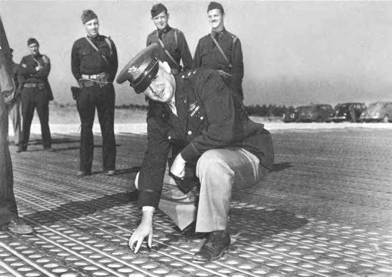
Maj. Gen. Henry H. Arnold, Chief of the Army Air Forces, inspecting a runway constructed of pierced steel plank, November 1941
power of construction machinery to move mountains and cut through jungle. In the steel treadway the Armored Force had a bridge which could be rapidly built to carry weights undreamed of in the mid-thirties. With the development of landing mats aviation engineers were furnished with a similar means of adjusting to the heavy loads of the newer bombers.
The effort to revolutionize equipment had had its share of opposition both within and without the Corps, but nothing even approaching a counterrevolution was ever imagined. The differences between various groups arose mainly because of the presence of strong personalities. The force with which they presented their arguments, whether radical or conservative, worked in the long run toward achieving a balance between the new and the tried.