Chapter 14: Antiaircraft Defense: Ground-to-Air Weapons
Developments in aircraft design following World War I opened up prospects of a type of warfare that would dwarf in significance all air operations of the 1914 -18 period. The Italo-Ethiopian War and the Spanish Civil War amply confirmed the importance of defense against bombing raids and focused attention of the United States Coast Artillery Corps and Ordnance Department upon the need of long-range, accurate, powerful antiaircraft guns. Though the Air Corps, tutored by Brig. Gen. William L. Mitchell, the famous Billy Mitchell, for a decade had nursed the belief that well-armed fighter planes would make antiaircraft guns superfluous, Ordnance officers foresaw the need of antiaircraft artillery as well as fighters.1 The 3-inch antiaircraft gun standardized in 1927 was a good weapon for use against aircraft of the 1920s but had neither the range to be effective against planes flying at the heights attainable by 1937 nor the fire control mechanisms needed to track accurately enemy craft flying at the greater speeds of the more modern planes. Even before the outbreak of war in Europe, American preoccupation with defense made logical the dedication of utmost effort to design of improved antiaircraft weapons. Later the Battle of Britain and realization of the overwhelming advantage that clearing the skies of enemy craft would give, when the time came for a full-scale offensive against the Continent, further stressed the wisdom of perfecting antiaircraft equipment of every kind—guns, mounts, tracking devices, and ammunition.
The problem of reaching targets flying at great heights did not loom large for antiaircraft batteries in World War II. Most enemy planes operated at not more than 10,000 feet and the 3-inch antiaircraft gun M3 had a slant range of 15,000 feet. Newer guns had much greater range.2 Command of necessary range by no means solved the problems of effective antiaircraft fire. It is important to remember that because airplanes, unlike ground equipment, operate freely in three dimensions, accurate fire control is as much more complex for antiaircraft guns than for ground weapons as solid geometry or spherical trigonometry is than plane geometry or trigonometry. Add to that complexity the factor of the speed at which modern planes fly—whereby the fourth dimension of time is introduced—and success in destroying
enemy planes by ground fire might appear to become a matter of luck. To convert chance into some predictable proportion of destructive hits to number of targets fired at was a challenge that the Ordnance Department faced through much of the war.
Of the various ways of meeting the challenge, a steady barrage of fire was one. Against low-flying craft, use of guns with rapid cyclic rates would increase the chances of a strike by sheer volume of fire. A machine gun, or better still batteries of machine guns, could saturate the path of the enemy plane with a rain of bullets, provided the gunners had estimated range, height, and direction correctly. But that method, necessarily employed under some circumstances, was extravagant of ammunition inasmuch as fire control on a machine gun could consist only of sights. Against high-flying planes machine gun fire was too short-ranged to be reliable. Furthermore, even a direct hit might lack destructive power if the energy of the bullet were nearly spent upon impact, if the plane’s armor plate were so heavy as to prevent penetration, or if upon penetration the projectile did little damage. Special ammunition was required to forestall those contingencies. Artillery, on the other hand, though having long range, power, and shell bursts covering a considerable area, could not fire fast enough to blanket the skies, even if guns were equipped with automatic fuze setter-rammers. As the skies are wide and a plane at any distance is a mere speck, the saturation technique manifestly was useful only for defense against close-in attack. In fact, every shot against moving planes. Ordnance experts had long realized, must be an aimed shot, whether fired from a machine gun or a larger weapon. British experiments in defending the Channel and London by sending up barrages of rockets were spectacular and thus helped civilian morale, but were of doubtful value because of rockets’ inaccuracy at that time. Since General Barnes considered antiaircraft rockets useless unless accuracy could be improved, the Ordnance Department abandoned its rocket development plans as soon as sufficient antiaircraft artillery became available.3
A more efficient way of improving antiaircraft fire, in the opinion of Army Ordnance, was to develop and employ ammunition and weapons of very high muzzle velocities. The greater velocity would flatten the trajectory of projectiles’ flight and, by lessening time of flight, insure a larger proportion of hits. Supervelocity, however, introduced the problem of excessive barrel erosion, and, as antiaircraft artillery shots, regardless of velocity, had to be aimed properly to be effective, tracking devices were essential. They might be electromechanical systems that computed firing data and directed the gun’s fire on the basis of optical observation, or they might employ radar linked with an electronic computer that transmitted the data to electric controls on the gun’s mount. Both types of director would greatly assist in keeping on the target. Finally, fuzes calculated to function only when within a given distance of the enemy craft would guarantee a large number of lethal strikes regardless of the plane’s speed. Use of all these means in combination promised the
most nearly foolproof system of antiaircraft defense conceivable, and before the war was won employment of that combination brought deadly results. Whereas one hit in every 2,500 artillery shots was average in 1940, that ratio in some engagements was reduced to about one in every 300 by late 1944.4
Volume of Fire for Defense Against Low-Flying Aircraft
Machine Guns
For saturating fire against strafing attacks the ,50-caliber machine gun was regarded by both the Ordnance Department and the using arms as a satisfactory weapon. The ,30-caliber machine gun was too light to serve under most circumstances, though for training it answered as well as the .50-caliber and was cheaper to use. In the 1930s the Coast Artillery, then the arm concerned with antiaircraft defense, preferred the .50-caliber water-cooled gun, the basic M2 equipped with an outer water-filled jacket and a water pump for cooling the barrel. Yet because a water supply might be hard to maintain under some combat conditions, an air-cooled heavy-barreled model was also designed for ground use where long bursts of fire might be necessary. The added amount of metal in the barrel absorbed heat just as water-cooling dissipated it. To increase velocity and accuracy and to reduce flash and smoke, the barrel was lengthened from 36 to 45 inches for the heavy-barreled and the water-cooled models in 1937 and 1938, respectively.5 The former, firing 400 to 500 rounds a minute, the latter, 500 to 650, had both proved their dependability, and attempts to increase greatly those cyclic rates threatened to impair efficiency and durability. Though early in the war the rate on each type was successfully pushed about 50 rounds a minute higher, and increase in belt-lift capacity was achieved in 1944, most improvements were minor. Smoother functioning also resulted from improved manufacture, as producers learned how to provide better finishes and eliminate interferences between moving parts. In the last months of the war an experimental barrel lightened from 28 to 20 pounds permitted considerably faster rates of fire. But by that time the danger from enemy aircraft had so lessened that the Ground Forces believed the added wear on the barrel too great to warrant establishing a requirement for the faster-firing gun.6
If .50-caliber antiaircraft machine guns themselves required few changes after 1940, their mounts were another story. The tripod mount adopted in the 1930s had been designed for a different tactical use from what the changes in air warfare demanded in 1940. By then, the Chief of Coast Artillery labelled existing mounts too heavy, too hard to transport, and having insufficient elevation to be suited to close-in defense against low-flying, high-speed targets. Complex sighting devices for tracking at ranges beyond a thousand yards were no longer necessary for machine guns. A mount capable of being transported in and fired from a ¼-ton or 1½-ton truck would have to be
considerably lighter than the 500-pound mount then standard. Upon the basis of two designs prepared after careful study by Rock Island Arsenal, the Heintz Manufacturing Company of Philadelphia in 1942 built an acceptable model which was standardized as the M3. The new mount weighed 380 pounds including the armor-plate shields for the gunner, had the desired elevation of—15 to 90 degrees, and a simple ring sight. Early in 1943, before the M3’s were available, the need for antiaircraft equipment became so urgent that some improvisation was imperative. Specially designed elevator cradles that could be affixed to existing ground mounts permitted using for antiaircraft defense the thousands of heavy barreled caliber .50’s in the hands of troops in all theatres. The cradle, standardized in August 1943, was light, sufficiently stable, and readily attached to the tripod ground mount. Though these elevator cradles were a makeshift, the 80,000 put into service before midsummer of 1944 supplemented the supply of antiaircraft mounts at a time when strafing planes were a threat in every theatre of operations.
Meanwhile, the Airborne Command requested mounts that could be put into action faster than the standard M3. Search for a mount weighing less than 160 pounds, transportable by two men, and possessing good stability, went forward during 1943 and culminated in a satisfactory model, the M63, in May 1944. The M63 was based on a Heintz Manufacturing Company design that Maj. John H. Kochevar of the Airborne Command modified by supplying a quadruped base with horizontal legs and a folding, T-shaped trigger extension attached to the cradle. It weighed only 144 pounds. Nearly 48,000 were produced before V-J Day and filled the need for mounts that could be airborne, landed from small boats, or carried into places inaccessible to vehicles.7 For protection to ships and landing craft, mounts were assembled with pedestal bases that could be bolted to the deck. The Army for the most part adopted Navy models for use on tank lighters and similar craft needing antiaircraft machine guns.8
As volume of fire could be increased not only by more rapid rates of fire but also by multiplying the number of guns trained upon a target, multiple mounting of caliber .50’s was recognized early in the war as a sound method of adding to the protection of moving convoys. The first multiple machine gun carriage completed in 1942 was a 4-wheeled trailer on which 4 heavy-barreled caliber .50’s were placed on a power-driven armored mount having a self-contained power unit. A turret, resting on a steel base plate anchored to the floor of the trailer, provided 360 degrees traverse. The turret could also be emplaced in a half-track to make a self-propelled unit. A centrally located gunner’s seat was situated between two trunnion sectors, each of which supported two guns and two 200-round ammunition chests. A sight base with a reflector sight, the ME IX developed by the Navy, moved with the trunnions. The guns were normally fired electrically but, in event of power failure, could be fired by a hand mechanism. In 1943 a variation of this M51 carriage was designed for airborne use. A portable 2-wheeled trailer mount, light
and compact enough to be stowed in a C6-4A glider or a C-47 transport plane, was equipped with mechanical jacks permitting rapid emplacement and leveling for firing once the trailer wheels had been removed. In most features identical with the mount of the M51 carriage, the mount on this M55 model provided a special armor shield and a handlebar control of turret movement and firing.9 Still more effective for some purposes than quadruple .50-caliber mounts was a combination of two water-cooled machine guns and a 37-mm, automatic gun in a special cradle mounted on a half-track.10 This mount, standardized as the 37-mm. antiaircraft M15, was appraised in a report from North Africa.
The proficiency of this mobile weapon can be attributed to three characteristics: its mobility enabling it to work well in close support of combat troops in forward areas and also to effectively patrol roads over which heavy traffic must travel under constant threat of bombing and strafing; its flexible fire power combining the volume of caliber ,50 with the knocking power of the 37-mm.; and the facility with which its fire is controlled by using the tracer stream of one caliber ,50 to bring it on the target before opening with the full volume of its armament. Numerous cases are cited where a ‘mouse trap’ effect has been obtained when enemy planes came in much closer on the initial caliber .50 fire than they would on light cannon and are caught by the 37-mm.11
Improved Ammunition
The destructive effect of antiaircraft machine gun fire depended quite as much upon the type of ammunition used as upon velocity or volume. Though there was some difference of opinion about the value of tracer, the using arms tended to believe it was an aid to accuracy. Certainly penetration could be improved by use of armor- piercing ammunition, and deadliness by employment of incendiary. A cartridge embodying all those features could be the most desirable of all. Between 1940 and 1942 Ordnance experts investigated the possibilities of explosive bullets but development of better types put an end to this work.12 Thanks to an Ordnance development program of the 1930s, one kind of tracer armor-piercing cartridge was available for small arms in 1940. As the war progressed some work was expended on developing special .30-caliber ammunition for machine guns,13 but most .30-caliber armor-piercing ammunition was used in rifles and carbines in place of ball ammunition. After mid-1943 antiaircraft batteries used the smaller weapon only rarely and the Army Air Forces never. Hence the discussion that follow deals largely with caliber .50’s and artillery.
The most urgent requests for improved .50-caliber ammunition from 1940 onward came from the Air Forces.14 But the Antiaircraft Command was also concerned, particularly after the Lend-Lease Act made British problems and experience in antiaircraft defense a strong consideration.
British faith in tracer ammunition fortified the belief of the American Antiaircraft Command in the usefulness of tracer to guide machine gun fire. The trajectory of a tracer bullet is visible for a given distance because a chemical element incorporated in the cartridge provides a trail of flame or smoke. Consequently, in response to a series of requests, throughout the war Ordnance technicians undertook dozens of research projects on various types of tracer to supplement the one kind available in 1940. But lack of agreement among the using arms about what characteristics were essential resulted in the Ordnance Department’s spending much money and effort to produce a great number of types, many of which’ were never adopted for combat. Though down into 1944 the Antiaircraft Command used the .50-caliber M1 tracer, standard in 1940, late in 1942 the command headquarters requested a cartridge with a bright trace increased from 2,000 to 2,500 yards. The argument of the Antiaircraft Board was that the greater length of trace would enable the .50-caliber machine gun used as a subcaliber weapon on 37-mm, and 40-mm. guns to duplicate more nearly the effect of fire of the larger guns. The desired features of lengthened trace and minimum flash at the gun were successfully achieved in a cartridge standardized in July 1944 as the M17. This replaced the M1 for antiaircraft use until March 1945, when a still better cartridge, the M20, was available. The M17 continued to be used for training even after the war.15
Whatever its value for improving accuracy, tracer alone lacked power to pierce armor plate and therefore was ineffective against the armored planes and the self-sealing fuel tanks employed by the Axis Powers. Even armor-piercing cartridges frequently failed to do much damage. Thus, the need for ammunition of greater lethal effect was apparent a year before the United States became a belligerent. British experience pointed to the usefulness of incendiary. The first .50-caliber incendiary, the M1, was designed for air combat, but antiaircraft batteries also used it for a time while awaiting development of an armor-piercing-incendiary bullet requested in the fall of 1942 for ground use. Study of a Soviet 13.2-mm. and an Italian 7.7-mm. armor-piercing-incendiary assisted Frankford Arsenal in devising a cartridge with an armor-piercing core inserted into the M1 incendiary bullet jacket. The bullet weighed 649 grains, and 14 grains of a special incendiary mixture were added in the bullet jacket. Tests during 1943 proving it satisfactory, the new armor-piercing-incendiary cartridge was adopted under the designation M8.16 Thereafter the Ground Forces used a linkage of four M8 cartridges to one tracer.
A single cartridge incorporating armor-piercing, incendiary, and tracer characteristics had not yet been evolved. The Ordnance Department began experimenting with a modification of the M8 late in 1943. By omitting the lead base filler used in the M8, adding several more grains of incendiary mixture, and inserting in the base of the core a new tracer mixture, Ordnance experts had an armor-piercing-incendiary tracer model ready for service tests by June 1944, when the Air Forces established a requirement for ammunition
of this kind. While preparations were under way for manufacturing a large quantity for combat test, the Ordnance Department furnished samples to the Antiaircraft Board as well as to other boards of the services and to the Navy. For aircraft use, this T28 had indisputable value, but whether it would meet the needs of the Ground Forces was uncertain. The findings were universally approving. The Antiaircraft Board pronounced the trace features superior to those of the M1 tracer, because the initial trace was dimmer and the smoke along the trajectory less. Since the armor-piercing-incendiary characteristics added deadliness, the Commanding General, Army Ground Forces, recommended standardization. The cartridge was designated the caliber .50 armor-piercing-incendiary tracer M20. Its drawbacks were two: the complexity of design made manufacture difficult, and the chemical composition of the ammunition led to rapid deterioration in storage. The second fault was common to all tracer ammunition, and the demand for the M20 was so great that no problem of prolonged storage arose during the war. The hitch was rather one of keeping supply somewhere near the level of demand, a problem rendered acute by the difficulty of manufacture. But the M20 gave both Ground and Air Forces a tracer cartridge with ballistic performance identical with that of the round for which the tracer served as fire control. Time of flight of the M20 was exactly that of the M8 armor-piercing-incendiary at all points of the trajectory.17 The adoption of the armor-piercing-incendiary tracer marked the peak of accomplishment in machine gun ammunition used against aircraft during the war.
Artillery Fire for Defense Against Close-in Attack
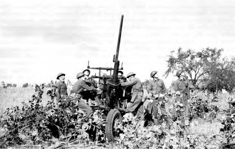
37-mm. Guns
The limitations of machine guns made light artillery essential for defense against relatively close-in attack. Light artillery could be equipped with fire control mechanisms that could not be used on machine guns; and an artillery projectile, if only because of its far greater mass, could destroy a target that machine gun bullets might hit without seriously damaging. After World War I, by general agreement, a project was given high priority to develop an antiaircraft gun of about 37-mm. caliber to fill the gap between machine guns and comparatively slow-moving intermediate and heavy artillery. Ordnance designers, assisted by John Browning of machine gun fame, and later by the Colt’s Patent Fire Arms Company, pushed forward work upon a 37-mm., and, after standardization of a model in 1927, Watertown and Frankford Arsenals carried on development of a carriage and sighting system. Yet progress was slow, particularly on the fire control and sighting devices, which were of considerable complexity and not very satisfactory in operation. Nevertheless, by the fall of 1938, as the war was drawing closer, a carriage, standardized as the M3, and a sighting system, M2, coupled with a so-called control equipment set, the M1, were put into production, while orders for the gun itself went to Watervliet Arsenal and Colt.
The next two years saw numerous modifications. The muzzle velocity of the gun was lowered to prevent premature bursts
from new self-destroying tracer ammunition and to lessen barrel erosion; and before 1940 was out, the sighting and control system was scrapped in favor of a British development, the Kerrison predictor and “oil gears.” The latter were electro-hydraulic power-control units mounted on the carriage and linked by an electrical data transmission system to the mechanical director; the separate, off-carriage Kerrison predictor computed the firing data as it tracked the target.18 This British remote control system, originally designed for use with 40-mm. Bofors guns, was so undeniably superior to the American that the Ordnance Technical Committee recommended adopting the British type for all new 37-mm carriages. So equipped, the carriage was designated the M3A1. While tracer shell alone was a poor substitute for an accurate tracking system, a tracer element was incorporated in all 37-mm. ammunition. If the director failed to work, the tracer would still provide some fire control, and at all times would provide a check upon the accuracy of the tracking mechanism. Moreover, when the combination mount M15 was put into service, its two .50-caliber machine guns helped to keep the 37-mm. on the target as well as to increase volume of fire.19
40-mm. Bofors
Meanwhile the 40-mm. Bofors had shown its capabilities. The carriage of the Bofors differed little from the American. The gun itself, in the opinion of many experts, was a better weapon than the 37-mm. in several respects. The British strongly advocated adopting the 40, and it was obvious that manufacturing facilities were too few to produce both 37’s and 40’s in quantity. The Swedish Bofors gun and carriage together weighed some 575 pounds less than the 37-mm. mounted on its carriage. The Bofors was somewhat similar in design, fired a projectile half again as heavy at 270 feet per second higher muzzle velocity, and had a slightly faster cyclic rate than the 37-mm. An automatic loading mechanism fed cartridges into a loading tray from which they were pushed into the chamber by a mechanically operated rammer. Though the 40-mm, barrel when fired at a rate of 140 rounds per minute tended to overheat, a new barrel could be emplaced in about two minutes. The 4.3-mile range of the foreign weapon exceeded the 6,200-yard maximum range of the American, but use of the director actually limited effective range of the Bofors to about 3,000 yards. Still, in many situations the advantages of the director more than offset the reduction of range.20
Endeavors in 1937 to purchase Bofors for test had come to nothing, owing to a series of mishaps.21 Not until the fall of 1940 did the United States obtain models, the Navy one in October, the Army one in December. Only close collaboration between the Army, the Navy, and the British enabled the United States to hasten negotiations for manufacturing rights and the Ordnance Department to get drawings and construction of two pilot models
Antiaircraft Guns
37-mm
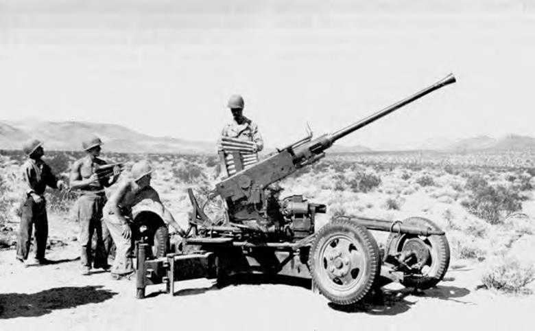
Bofors 40-mm
started even before contracts with the Swedish company were formalized. The Army officially adopted the air-cooled Bofors as the 40-mm, automatic antiaircraft gun M1 in April 1941, with the explicit statement that as soon as quantity manufacture was achieved, the 40-mm. was to supersede the 37-mm. antiaircraft gun.22 That moment was not reached until the summer of 1943, a delay that had been prolonged by the necessity of transposing the metric measurements of the foreign drawings to United States Ordnance standards. Minor changes resulted from tests in the summer of 1942. The most important was the decision to follow British practice and the original Bofors design of increasing the twist of the rifling from one turn in 45 calibers at the breech to one turn in 30 at the muzzle. The increasing twist lengthened accuracy life from 4,200 service rounds to approximately 6,000.23
All Bofors ammunition was in the form of fixed rounds, either armor-piercing with tracer or high-explosive shell. Before midsummer 1943 American manufacturers found it hard to make. The British percussion fuze, in particular, was so complex that as early as January 1942 the Ordnance Technical Committee recommended substitution of a simple plunger type of point-detonating fuze similar to those the Ordnance Department had long used. Before this PD fuze M64 got into quantity production, the Navy was turning out its Mark 27 PD fuze which answered the same purpose. Consequently the Army also used the Mark 27 with high-explosive shell, though in the interests of more economical manufacture, the Ordnance Department developed another PD fuze, the M71.24
Both mount and carriage also were somewhat modified, partly to ease manufacture and maintenance, partly to improve performance. The Firestone Tire and Rubber Company, who accepted the contract for the first pilot models, succeeded in producing a welded frame to replace the riveted construction of the original mount, a far more efficient and easily fabricated bearing for the traverse mechanism, cheaper and more easily installed bushings for bearings, and steel tubing instead of forged and machined axles. The carriage was modified by adding four-wheel electric brakes and a few other improvements. Some slight differences between the model manufactured for the British and that for the US Army led to assigning the nomenclature M2 to the latter carriage, M1 to the lend-lease model. To increase the tracking rate in following a high-speed target approaching from an unexpected direction at short range, new gears with a higher gear ratio were installed in the carriage, now labeled the M2A1. Addition of “cartwheel” sights was another improvement. The diameter of the forward ring was first increased to provide for leading a target traveling at 300 miles an hour at a 1,000-yard range and later was increased to cover targets moving at 400 miles an hour.25
As combat experience in North Africa emphasized the need of combining maximum fire power and mobility with a minimum number of vehicles, in 1943 various combination mounts on both half-tracks
and tank chassis were tried out—twin 40-mm. guns, a 40-mm. gun together with two .50-caliber machine guns, and twin 40-mm, with twin machine guns. Any of these promised to increase volume of fire considerably. The most satisfactory proved to be two 40-mm. antiaircraft guns mounted on the chassis of the light tank M24, in 1944 designated the M19 twin 40-mm. gun motor carriage.26 Experiments with mounting a 75-mm. antiaircraft gun on this carriage began early in 1945 but were incomplete by the end of the war. For airborne use, a somewhat lightened 40-mm. carriage, the M5, was developed. The gun barrel and detachable outriggers had to be removed before loading into a transport plane but, after landing, three men could emplace the carriage in five minutes.27
At one stage of the war, after manufacture of 37-mm. antiaircraft guns had stopped, the question arose of whether a weapon between the .50-caliber machine gun and the 40-mm. gun would not be an advantage. Both the Germans and the Italians used 20-mm. ack-ack, but always with ammunition containing a self-destroying feature which neither British nor American 20-mm. ammunition possessed. The danger of serious casualties to Allied troops, unless fire were only over water, was too great to risk. Furthermore, theatre reports in 1944 indicated no real need for an antiaircraft gun at once more powerful than a caliber .50 and lighter and smaller than the Bofors.28
Defense Against Fast-Flying Aircraft at High Altitudes
Longer Range: Rockets
High-flying enemy bombers and protecting escort planes had if possible to be brought down before crews unloaded the bombs. For that purpose light artillery such as the 37-mm. and 40-mm. guns had insufficient range and power. Powerful ground fire, as both American and British Ordnance experts knew, was a vital supplement to Allied fighter craft, particularly early in the war when American, British, and Russian planes were outnumbered by enemy. In the spring of 1941 the Ordnance Department requested NDRC to investigate the use of jet propulsion for antiaircraft projectiles in order to shorten time of flight, increase vertical range, and simplify the projecting weapon. Work on the fundamental research this project involved had not gone far when it got fresh impetus from Dr. Lauritsen, vice chairman of one of the NDRC divisions. The British had invested a great deal of effort and money in getting antiaircraft rockets into action because, after Dunkerque, artillery was in extremely short supply, and 3-inch unrotated rocket projectiles and launchers had been developed to the point where they could be used. British “UP-3’s” when fired with time fuzes had a ceiling of about 22,000 feet. Because the potentialities of these antiaircraft rockets greatly impressed
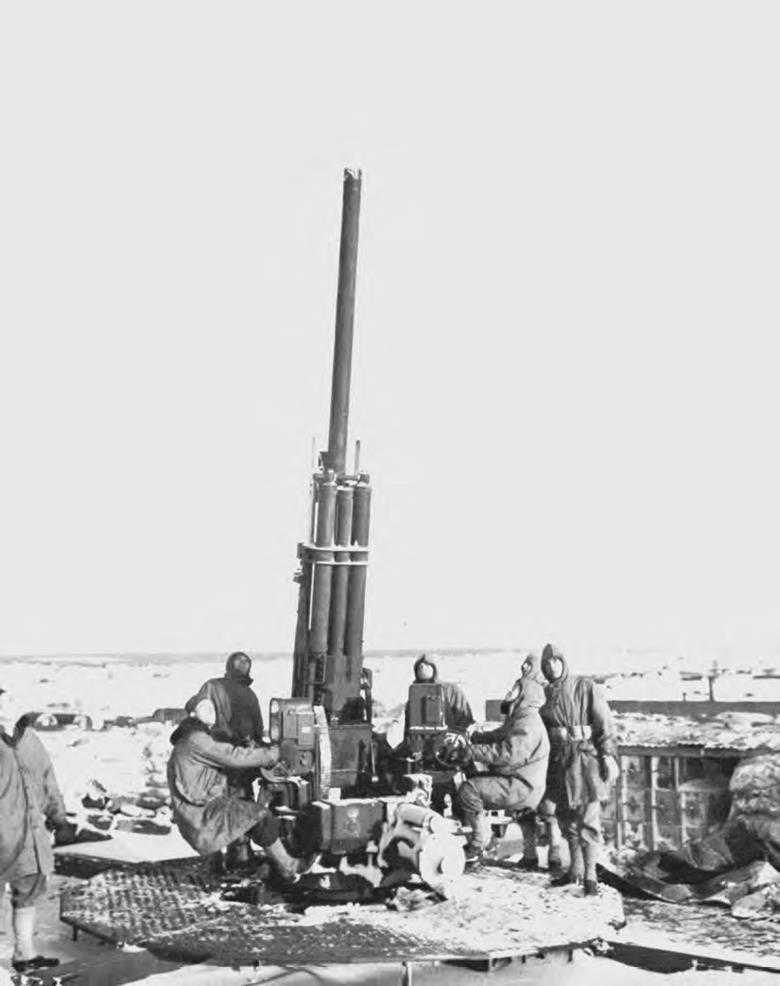
90-mm. Antiaircraft gun during a practice alert in Iceland
Lauritsen, the NDRC representative in London in the summer of 1941, the American armed services after study of Lauritsen’s report contracted with the California Institute of Technology to carry this development further. The resulting work upon rocket propellants was valuable for other purposes but was not put to use for antiaircraft rockets since, by the time the necessary preliminaries were finished, powerful long-range artillery was available in quantity. The greater accuracy and higher velocity of rifled guns made antiaircraft rockets needless. From the California Institute of Technology, however, did come the data that enabled the Ordnance Department to produce the 3.25-inch target rocket which was of help in training antiaircraft gunners.29
Longer Range: The 90-mm. Gun
Long before the United States had so much as considered antiaircraft rockets, the Ordnance Department had been working upon powerful long-range artillery. Though the 3-inch gun M3 did in fact command adequate range for most World War II antiaircraft defense, and though it served the US Army well on Bataan, its muzzle velocity of only 2,600 feet per second and its light, 12.8-pound projectile were drawbacks. Aware of these shortcomings, in 1938 the Coast Artillery had requested a larger-caliber gun, with a higher muzzle velocity, capable of firing a 21-pound projectile to a greater height than the 3-inch could reach. Since a Coast Artillery Board report of 1939 spoke of bombers flying at 250 miles per hour at an altitude of 32,000 feet and of even faster craft under design which could operate at a ceiling of nearly eight miles, 1939 saw the start of work upon a still longer- range gun calculated to reach planes at heights of 56,000 feet.30
The 1938 project, a 90-mm. antiaircraft gun, was rushed to completion in 1940. The selection of that caliber had been determined by the weight of a shell that could be hand loaded; anything in excess of forty pounds for a complete round would be too heavy for men to handle for more than a few minutes at a stretch, and mechanical loading systems up to that time had not been reliable. To obtain greater stability and a self-cocking firing mechanism, several changes in the original design of both mount and gun were effected in late 1939 and early 1940. As tests showed the modifications to be adequate, gun and mount were standardized in February 1940.31 Almost at once, however, a fuze setter and spring rammer was hurried into production to facilitate ammunition loading. In the field, gunners usually disconnected it, as crews thought hand-ramming faster and considered the spring rammer dangerous because it sometimes struck the loader or mashed his fingers. The spring rammer was admittedly a
stop-gap until a better, albeit more complicated, mechanism could be perfected. An electrically controlled rammer and fuze setter required linkage with mechanical or electric directors.
When the automatic fuze setter-rammer developed by the United Shoe Machinery Company was accepted by the Ordnance Department, the potential rate of fire of the 90-mm, gun increased. But it never got above 27 shots per minute, even in practice firing. This electrically controlled fuze setter-rammer, designated the M20, was ingenious. The crews fed a complete round of ammunition into slowly rotating ramming rolls that drew the round into the fuze setter jaws. There it stopped until the jaws received the position signal from the remotely located electric director and then rotated the fuze to set it as directed. Thereupon the jaws opened and the round was automatically rammed into the breech, the breech closed, and the round was fired. This decreased the “dead time” between setting the fuze and the moment of firing. As a fast-flying plane could move a considerable distance in that interval, use of the automatic fuze setter-rammer notably improved accuracy.32 Only hypervelocity, largely a matter of ammunition with flatter trajectory, could further multiply efficiency of the gun itself.
The Search for High Velocity
The 90-mm. was to have been a high-velocity gun and, at its inception in 1938, its proposed 2,800 feet per second might have been called high velocity. The German 88-mm. Flak 36 had a muzzle velocity of 2,690 feet per second. Unhappily, the walls of the first shell designed for the 90-mm. proved to have insufficient strength to withstand the pressures upon them when the rotating bands engaged the rifling. Special heat treating would give the needed strength, but in 1941 manufacturing capacity for that process was too limited to count upon. The alternative was to increase the thickness of the shell walls, a change that increased weight and reduced the amount of explosive charge, thereby decreasing muzzle velocity to 2,700 feet a second. When the German 88-mm. Flak 41 gun with its velocity of 3,280 feet per second and its high-explosive ammunition appeared, the American 90 was outclassed in that particular. Unlike field guns, antiaircraft artillery never fired in direct competition with enemy ack-ack. If the American gun brought down its target, it mattered little that the gun was less powerful than its German counterpart. Yet the challenge of the German guns remained.33 The 90-mm. M2 was, to be sure, so mounted as to enable it to fire at tanks and other ground targets, a versatility that won it the label of “triple threat” gun. But it was the 90-mm. M3, designed specifically for antitank use, that was pressed into use as a field gun. Velocity of the AA gun never got above 2,700 feet per second.
The difficulty for the US Army was partly logistical. Increased velocities spelled excessive barrel wear unless erosion resistant gun tubes could be developed or powders combining high-potential with a cool-burning, noneroding chemical composition. For Germany, with her interior lines of supply, barrel replacement was
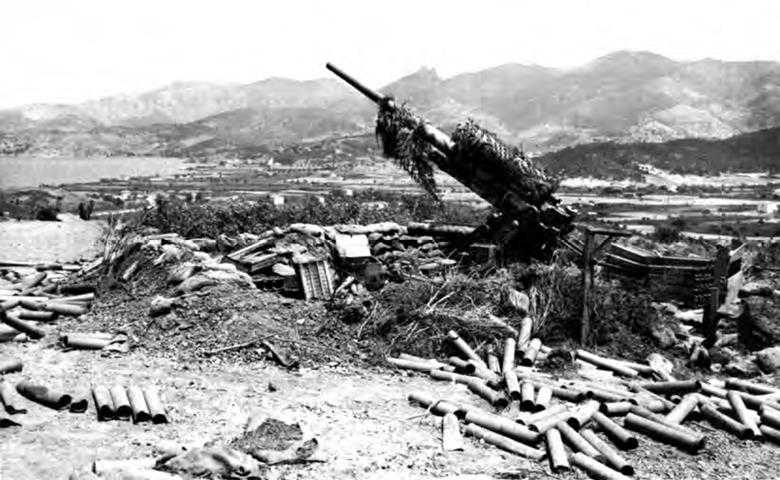
German 88-mm. at Porte Ferraio, Elba. This was the multipurpose artillery piece of the German Army.
very much easier than for the Allies, whose matériel had to be shipped from the States. The official German weapons handbook gave an estimated life of 1,500 rounds to the 88-mm. Flak 41 gun, 2,000 to 2,500 rounds with supercharges to the Flak 36 and 37.34 Life of the 90-mm. antiaircraft guns was limited to about 1,600 rounds because the mechanical time fuzes ordinarily used failed to function properly after the barrel was somewhat worn. Yet in firing against German V-1 missiles in the summer of 1944, experience showed that, with VT fuzes, life of barrels might be extended to 1,900 rounds, depending upon how rapid the rate of fire was and how long sustained. On the problem of achieving hypervelocity without creating an impossible maintenance situation, the Ordnance Department and its contractors throughout the war expended much time, effort, and money.35
Inasmuch as practicable solutions would depend upon considerable basic research into the mechanics and chemistry of barrel erosion, the Ordnance Department requested NDRC to undertake a comprehensive study of the problem. The work, under the guidance of Dr. L. H. Adams,
was primarily important because of the solid foundation of knowledge it laid down upon the causes of erosion. But NDRC’s sixteen contractors on this project—re-search institutions and private companies—also contributed by exploring various applications of this knowledge. While NDRC success in developing liners for machine gun barrels36 was not duplicated for artillery, some inconclusive experiments were tried: using replaceable steel liners for artillery, employing pre-engraved projectiles so as to lessen the friction between the projectile and the lands of the rifled bore, and a protecting metal sleeve to be fitted over the junction of the cartridge case and the projectile. More promising were the studies of erosion-resistant materials, notably molybdenum and hot-hard alloys, and the sabot projectile developed for the 90-mm, gun. But as the NDRC project was concerned with the over-all problem of hypervelocity, in May 1944 the Ordnance Department began work on hypervelocity specifically for 3-inch, 90-mm., and 105-mm. antiaircraft fire.37 V-J Day arrived before this development program had made much headway.
Indeed, the only high-velocity American antiaircraft gun, the 120-mm., saw little action, partly because its development and production lagged by more than a year behind that of the 90-mm,, and partly because its weight made transport difficult. Nevertheless, even in 1939 the Ordnance Department had been convinced that a more powerful antiaircraft weapon than the 90-mm. would in time be needed. Design of the 90-mm. was scarcely off the drawing boards when the Ordnance Department persuaded the Coast Artillery Board of the wisdom of having Ordnance develop a heavy antiaircraft gun. Whereas the limits of fire control in 1938 had pre- eluded the use of a longer-range gun than the 90-mm., by 1939 developments in radar and electronics held out hopes of effectively reaching to greater heights. The project accordingly launched in June 1939, though modified somewhat during the next sixteen months, called for a gun with a muzzle velocity of 3,100 feet per second, and able to fire a 50-pound projectile to an altitude of 56,000 feet. The ammunition had to be semifixed, that is, the 50-pound projectile separate from the 51-pound sealed powder case. As 50-pound loads would be too heavy for hand loading, a power-operated ammunition tray and rammer was necessary. These characteristics were incorporated in the model standardized in 1944 as the 120-mm, AA gun MI. An automatic fuze setter to ease and expedite firing permitted a rate of 10 rounds per minute. Ordnance designers regarded the 120-mm, as the best gun the Allied armies had for bringing down enemy aircraft at high altitudes. The 61,500-pound weight of the gun and mount was one objectionable feature, and the 123.5-inch width was another. Only 550 guns were manufactured and none was shipped to Europe. The 90-mm. and lighter weapons served as antiaircraft defense against the Luftwaffe.38
Fire Control and Tracking Devices
Guns, ammunition, and firing mechanisms were by no means the only elements
to consider in making the best possible antiaircraft equipment. Sighting, traversing, and elevating mechanisms, and tracking devices were equally essential. Machine guns with their limited range required only simple sights, and only when multiple-mounted on power-driven turrets were the guns electrically traversed. Fire control for heavier, more powerful weapons naturally had to be more complex. In fact, because the speed at which dive bombers and low-flying strafing planes operated made effective close-in fire more difficult than at long-range targets, devising accurate fire control mechanisms for light antiaircraft artillery was one of the knottiest problems Ordnance faced in 1940. Hand-tracking and aiming were likely to be inaccurate; the mechanical controls developed in the 1930s for the 37-mm. gun were clumsy and slow. The most satisfactory answer was found in the adoption of a British mechanical director linked with gears on the gun that automatically elevated and traversed the gun as the director transmitted its computations. The Kerrison predictor, named for its British inventor, Col. K. E. Kerrison, was somewhat modified for use with American guns, a task undertaken by NDRC. Later, addition of a stereoscopic range finder, an altitude converter, and an electric mechanism for setting slant range into the director’s multiplying mechanism produced the model labeled the M5A2 director. Improved oil gears to traverse and elevate the gun were also installed on the remote control system on the gun. Bofors sights on the 40-mm. and telescopes on the 37-mm. provided either for direct sighting or for use with the Kerrison predictor. On the 37-mm., one telescope to track in azimuth and one to track the target in elevation were attached to the top carriage and cradle so that each moved with the gun. Because the Kerrison predictors could not be mounted directly upon either the 37-mm, or 40-mm, carriage, they could not be used when the guns were moving to protect convoys or covering troops in forward areas. To permit aiming when the director was unusable, Frankford Arsenal developed a mechanical computing sight containing a mechanism by which the direction and speed of the target were set in. Parallel linkage of the two tracking mechanisms completed the computing sight.39
Directing fire of larger-caliber, heavier antiaircraft guns was only slightly less difficult. The original design of the 90-mm. lacked automatic controls. Manual operation of wheels to traverse and elevate rapidly a gun with a fifteen-foot barrel would require great exertion on the part of the gun crew, if indeed men at hand controls could keep on a fast-moving target at all. Consequently, though the Ordnance Department before 1940 had objected to automatic power controls as likely to be unreliable, it ran tests of a Sperry Gyroscope Company power system for the new 90-mm. gun during the summer of 1940. This first remote control system was, as Frankford Arsenal pointed out, “a complex combination of electrical, mechanical and hydraulic units,” which would be expensive to build, difficult to maintain in the field, and would double the load on the gun’s power generator.40 Nevertheless, despite defects, the apparatus did work and did provide a method of relative accuracy in laying guns against targets moving at
Fire Control Instruments
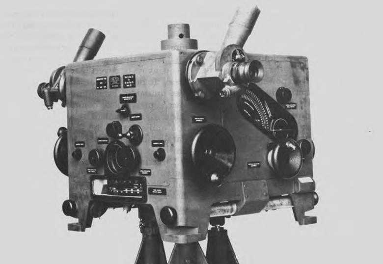
Director T30
Heightfinder M1
high angular speeds as well as against targets at short ranges where manual tracking was extremely difficult. In February 1941 the Ordnance Committee therefore recommended standardization of the Sperry servo-system as remote control system M2. To simplify its installation and servicing, some redesign followed. Extensive redesign was necessary for the mount in order to accommodate the controls. The new mount embodying these changes was designated the M1A1.41 It was a mobile unit resting on a single-axled, two-wheeled bogie drawn by a trail.
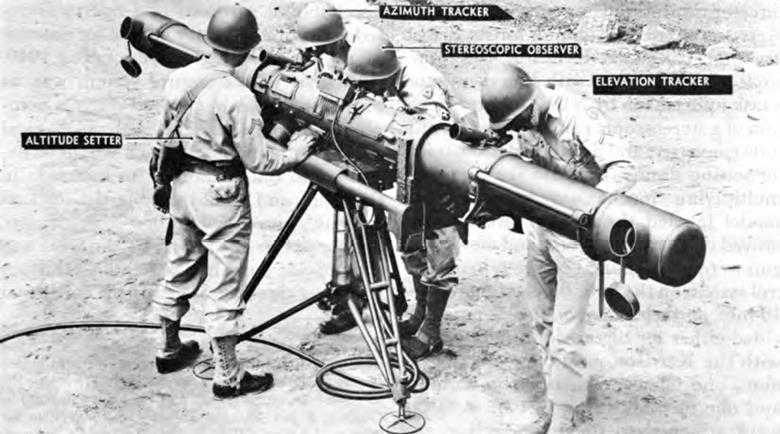
Sighting on the M1A1 mount was by elbow telescopes. Off-carriage equipment included a bore sight, as well as a height finder to determine the slant range or altitude of an enemy plane and to transmit the resulting data to the director. This telescopic device, largely perfected by the Eastman Kodak Company, was fundamentally a 13.5-foot stereoscopic range finder that converted slant range to altitude. The remote control system was linked by cable to an off-carriage mechanical director that computed the firing data continuously. Power was supplied by a separate generating unit located nearby.42 When the more elaborate fire control system for the 90-mm. gun M2 was developed, a good many changes in its mount were necessary, though it would have required some redesign in any case in order to install the fuze setter-rammer and the shields added to protect the gun crew. The gun itself differed from its predecessors only in minor details. The remote control system of the first 90-mm. models was replaced on the new mount by the M12 system, which permitted the gun to be depressed to -5 degrees so that it could be fired against ground targets and fast-moving torpedo boats. The greater weight of the M2 mount and gun, 32,300 pounds as compared to 19,000, demanded a two-axled trailer. The M12 remote control system operated on the same principle as the M2, from which it derived, but the M12 was connected with an electrical off-carriage director instead of with a mechanical director.43
The electric directors—the M9 series for the 90-mm. antiaircraft guns and the M10 for the 120-mm,—were extremely complicated devices. As they weighed about 3,500 pounds, they were installed in separate trailers. The major components of each director were a tracker, a computer, a power unit, and an altitude converter, all interconnected by a cable system. From the tracker, used only when the target was visible, data on range, elevation, and azimuth of the plane were transmitted to the computer. When the target was invisible, a radar system was used. The computer must seem to the layman to be a miraculous electric brain. The position of the target—its elevation, its azimuth, and its range at a given moment—was transmitted in polar coordinates to the computer, which transposed them to Cartesian, or rectangular, coordinates. As the speed at which the target was moving had to be taken into consideration to determine where to point the gun so that target and projectile would arrive at the same position in space simultaneously, the time element, introduced by velocity, had also to be figured. The computer mechanism made
continuous automatic electrical computations of firing data and transmitted them continuously to the gun. The advantages of electric directors over mechanical directors were several: improved tracking; complete ballistical solutions for nonstandard meteorological conditions of wind, temperature, and air density; the elimination of some errors inherent in the mechanical prediction system; a much shorter minimum slant range; and nearly twice the maximum horizontal range.44 Still the weight and bulk, as well as the complexity and cost, of this fire control equipment made it suitable only for big antiaircraft guns.
So intricate a device as the electric director did not, of course, spring like Athena whole from the head of Zeus. The proposal, conceived by Dr. D. B. Parkinson, came in June 1940 from the Bell Telephone Laboratories to the Chief of the Signal Corps who, after investigation of the rather detailed plan, pronounced it sound.
The story runs that Parkinson, who for some time had been interested in problems of fire control, dreamed one night of an electric computer that directed antiaircraft fire so exactly that as the “ping” of a fired shell sounded in the dreamer’s ears down came a plane, another ping and another plane fell—always one shot to a kill. Fascinated by the somewhat fantastic idea his dream had given shape to, Dr. Parkinson described it to his chief, Dr. Lovell, who recognized more than fantasy in it and directed his young assistant to try working out details.
Meanwhile, the creation of NDRC led the Bell Telephone engineers to approach Dr. Warren Weaver’s section, which was concerned with fire control. In September the enthusiasm over the plan evinced by members of the British Tizard Mission gave added impetus. As the problem involved automatic laying of the AA gun as well as use of radar for tracking the plane, the Ordnance Department took over from the Signal Corps. The specifications for a 90-mm, electrical director were worked out in the next six weeks, with the Ordnance Department, the Bell Laboratories, and NDRC collaborating. A year after formal initiation of the project, a first model was ready for the Coast Artillery test. NDRC’s contribution lay principally in its careful analysis of the mathematical problems involved. Some modifications of the pilot model followed, in keeping with Coast Artillery Board recommendations, but upon incorporation of these changes the director was standardized as the M9 in February 1942, only nineteen months after the inception of the idea. Though mathematically complex, the director was far easier to manufacture than the mechanical director it superseded. Many of the parts of the M9 and its later variations were standard commercial apparatus, and only where commercial parts lacked precision were specially made parts needed.45
Proximity Fuzes
While all other methods of increasing the proportion of effective antiaircraft hits were under consideration, the question arose of whether a fuze could be developed that would operate not by time but by proximity to the target. Impact-detonating ammunition would have been ideal for most antiaircraft fire had cyclic rates of
weapons been sufficiently high and fire control of greater accuracy. But early in the war the difficulty of computing the target’s range exactly led to reliance on mechanical time fuzes. These, if correctly set with proper allowance for dead-time, might explode the shell at the exact moment when the plane was within the cone of flying fragments, but in practice the burst was likely to occur anywhere along several hundred feet of shell path.46 Use of influence fuzes promised to improve the effectiveness of antiaircraft fire as much as any other single means conceivably could.47
For antiaircraft fire, two requirements of the proposed fuze were only less important than the primary stipulation that it function when passing within effective range of the target. Because antiaircraft batteries usually fired over friendly terrain, the fuze must have a self-destructive feature to guarantee that, in case of missing the target, no friendly troops or civilians would be injured or valuable equipment damaged. Secondly, the mechanism must have sufficient ruggedness to with stand the rotational and setback forces of antiaircraft weapons. Success in meeting these and the numerous other difficult requirements enabled the Army to issue proximity fuzes to AA batteries in the summer of 1944 when the German buzz-bomb attacks on England began. Forewarned of the impending attack, the Ordnance Department shipped the fuzes to the United Kingdom and stored them under guard until specialists had instructed AA gunners in use of what Lt. Gen. George S. Patton, Jr., later called the “funny fuze.” The result of the last four weeks of the V-1 bombings showed mounting effectiveness: destruction of 24, 46, 67, and 79 percent of the targets fired at. The British credited the proximity fuzes, together with American antiaircraft artillery, radar, and fire control, with saving London from the buzz bomb.48